
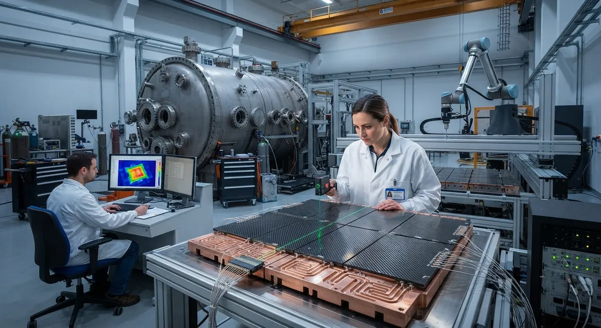
Nuclear fusion has moved from physics experiments to an engineering race, and carbon fiber composites are part of the material toolkit that makes the machines work. In a tokamak or stellarator, a plasma heated to over 100 million degrees Celsius is held away from the vessel walls by mag
Introduction
Nuclear fusion has moved from physics experiments to an engineering race, and carbon fiber composites are part of the material toolkit that makes the machines work. In a tokamak or stellarator, a plasma heated to over 100 million degrees Celsius is held away from the vessel walls by magnetic fields. But no magnetic field is perfect: some plasma always reaches the walls, and the walls must absorb heat fluxes that can exceed 10 MW/m² in the divertor region — comparable to the surface of the sun. Carbon fiber composites, particularly carbon-carbon (CFC) materials, are one of the few material families that survive these conditions, and carbon fiber reinforced polymers (CFRP) are increasingly specified for the support structures and cryogenic systems around the magnets.
For B2B buyers in the composite industry, fusion represents a small but fast-growing premium market with extremely demanding specifications. ITER in France, the SPARC and ARC programs in the United States, and a wave of private fusion startups are all procuring composite components. This article reviews the three main application areas — first wall and divertor components, magnet coil support structures, and radiation-resistant structural parts — and explains the engineering trade-offs that determine which carbon fiber grade and manufacturing route is specified.
First Wall and Plasma-Facing Components
The first wall is the innermost solid surface of a fusion reactor, directly facing the plasma. In current and near-term designs it is a water-cooled structure clad with armor tiles. The two candidate armor materials are tungsten and carbon-carbon composites. CFC materials have been used in operating tokamaks such as JET and ASDEX Upgrade because they combine several properties that metals struggle to match:
- Thermal shock resistance: CFC does not melt; at extreme heat fluxes it sublimes above 3,600 °C instead, avoiding the catastrophic melting failure mode of metals.
- High thermal conductivity: 2D and 3D CFC grades reach 100-400 W/(m·K) in-plane, approaching copper, which keeps tile surfaces cool under steady-state heat flux.
- Low atomic number: Carbon atoms entering the plasma cause far less radiation loss than high-Z impurities such as tungsten, which reduces plasma performance.
- Low coefficient of thermal expansion: Near-zero CTE means tiles do not distort under large thermal gradients.
The primary trade-off against tungsten is erosion and tritium retention. Carbon erodes faster under high-energy particle impact and traps hydrogen isotopes in its porous structure, which complicates tritium inventory management in a fusion plant. This is why ITER specified a full tungsten divertor while retaining carbon-carbon for areas where thermal shock is the dominant risk. For component suppliers, the key takeaway is that CFC demand is driven by high heat flux (HHF) testing qualification, not by volume — a typical divertor tile batch is small but certified to extreme standards.
Magnetic Coil Support and Cryogenic Structures
Around the plasma vessel, the magnets that confine the plasma generate enormous forces. The toroidal field coils of a large tokamak carry combined electromagnetic loads of hundreds of meganewtons, and these loads must be reacted by support structures operating at cryogenic temperatures around 4 K. Here carbon fiber reinforced polymers excel for a different reason: they combine high specific stiffness, near-zero coefficient of thermal expansion, and excellent fatigue resistance with thermal insulation properties.
| Application | Why Carbon Fiber | Typical Material Form | Key Requirement |
|---|---|---|---|
| Coil casing and intercoil structure | High stiffness-to-weight, CTE match with magnet materials | CFRP laminates, pultruded profiles | Fatigue life at 4 K, dimensional stability |
| Thermal breaks and standoff supports | Low thermal conductivity limits heat leak into cryostat | CFRP tubes and G10-type laminates | Thermal conductivity < 0.5 W/(m·K), load capacity |
| Cryostat and thermal shield structure | Lightweight, stiff panels for large vacuum enclosures | Sandwich panels with carbon skins | Low outgassing, vacuum compatibility |
| Diagnostic and feedthrough supports | Non-magnetic, radar-transparent behavior | Pultruded CFRP rods, machined plates | Non-ferromagnetic, low permeability |
Designers choose carbon fiber for these structures because steel alternatives are magnetic, heavy, and conduct heat into the cryogenic zone. A CFRP support structure can weigh 50-70% less than a stainless steel equivalent while offering comparable stiffness, and its low thermal conductivity reduces the refrigeration load on the cryoplant — a real operating cost in a reactor that must run continuously.
Radiation Resistance and Behavior Under Neutron Irradiation
Radiation resistance is the defining engineering constraint for fusion composites. Fusion neutrons are much more energetic than the neutrons in fission reactors — up to 14 MeV — and they cause two damage mechanisms in polymer matrix composites: displacement damage in the carbon fibers and degradation of the epoxy matrix. The behavior differs sharply between CFC (which has no polymer matrix) and CFRP:
- Carbon-carbon composites: Because the matrix is also carbon (deposited by chemical vapor infiltration or from a carbonizing resin), CFC retains structural integrity at very high neutron doses. The main effects are dimensional change — swelling then shrinkage — and a reduction in thermal conductivity at doses above 0.1 dpa. CFC remains the reference material for extreme-dose applications.
- Carbon fiber reinforced polymers: The epoxy matrix degrades under gamma and neutron irradiation. Gases such as hydrogen and carbon monoxide are evolved, the matrix embrittles, and interlaminar shear strength falls with increasing dose. Irradiation testing programs for fusion CFRP typically qualify materials to a specific dose (commonly 1-10 MGy for gamma plus neutron fluence) before they are accepted for coil support duty.
For suppliers, this means fusion-grade CFRP is a qualification-driven niche. Materials are procured with documented irradiation history, tight fiber areal weight control, and matrix systems chosen for radiation tolerance — often cyanate ester or specially formulated epoxies rather than standard aerospace grades. The certification pathway mirrors aerospace but adds radiation testing, which only a handful of test facilities worldwide can perform.
Manufacturing Routes and Quality Requirements
The manufacturing route depends on the component. Divertor and first wall CFC tiles are produced by a specialized route: 2D or 3D woven carbon preforms are densified by chemical vapor infiltration or liquid precursor impregnation, then graphitized at over 2,000 °C. The result is a material with no polymer left in the structure. Tile joining uses active metal brazing or a compliant interlayer to a copper alloy heat sink, and every tile is non-destructively tested — typically by ultrasonic inspection and X-ray computed tomography — before acceptance.
Magnet support and cryogenic CFRP parts use conventional composite manufacturing: autoclave curing of prepreg for laminates, filament winding or pultrusion for tubes and profiles, and CNC machining for brackets and standoffs. The distinguishing feature is the quality system. Fusion buyers apply aerospace-level traceability, dimensional inspection at cryogenic temperatures, and leak testing for vacuum-facing parts. Thermal cycling tests between 4 K and room temperature are routine acceptance criteria because differential contraction between carbon fiber and metallic inserts is a common failure mode.
Market Outlook and Supply Chain Implications
The fusion composite market is small in tonnage but strategically significant. ITER has driven qualification of CFC and CFRP materials for two decades, and the new wave of private fusion companies — high-field tokamaks using high-temperature superconductors — is creating demand for large, lightweight coil structures that only carbon fiber can deliver. Industry projections suggest fusion capital expenditure will grow substantially through the late 2020s and 2030s as pilot plants move toward construction, with composite content per reactor running into the tens of tonnes for support structure alone.
For carbon fiber producers and fabricators, the entry requirements are clear: irradiation-qualified material data, cryogenic test capability, and the discipline of a nuclear-grade quality system. The volumes are modest, but the margins and the credibility premium are high, and a fusion qualification opens doors to other extreme-environment markets including space launch and high-energy physics.
Frequently Asked Questions
Why is carbon-carbon (CFC) used in fusion reactors instead of metal armor?
CFC does not melt — it sublimes above 3,600 °C — so it survives thermal shocks that damage metals, and it has in-plane thermal conductivity approaching copper (100-400 W/(m·K)) plus near-zero thermal expansion. Its low atomic number also reduces plasma radiation losses. The main drawbacks are erosion under high-energy particle impact and hydrogen isotope (tritium) retention, which is why designs such as ITER use tungsten for the full divertor and reserve CFC for thermal-shock-critical areas.
How does neutron irradiation affect carbon fiber reinforced polymers?
Fusion neutrons (up to 14 MeV) degrade the epoxy matrix: they cause outgassing of hydrogen and carbon monoxide, matrix embrittlement, and falling interlaminar shear strength with increasing dose. The carbon fibers themselves suffer displacement damage but degrade more slowly. Fusion-grade CFRP is therefore qualified to a specific radiation dose (commonly 1-10 MGy gamma plus neutron fluence) with irradiation test data before acceptance for coil support duty.
What is the difference between CFC and standard CFRP in a reactor context?
CFC (carbon-carbon composite) has a carbon matrix deposited by chemical vapor infiltration and is graphitized above 2,000 °C — there is no polymer left, so it withstands extreme heat fluxes and very high neutron doses. CFRP uses a polymer matrix (epoxy or cyanate ester) and is used where structural stiffness at cryogenic temperature is required, such as magnet coil supports and thermal breaks, with radiation dose limits defined by matrix degradation.
Are carbon fiber structures in fusion reactors magnetic?
No. Carbon fiber composites are essentially non-magnetic, unlike steel, which is a critical advantage in a reactor where stray magnetic fields would distort the confinement field. CFRP supports, standoffs, and instrumentation structures can be placed close to the magnets without perturbing the field, which is one of the reasons designers specify them despite the qualification effort.
Conclusion
Carbon fiber composites serve fusion reactors in two distinct roles: carbon-carbon tiles that face the plasma and survive thermal shocks no metal can tolerate, and CFRP support and cryogenic structures that hold the magnets with minimal weight and heat leak. Radiation resistance is the defining qualification hurdle, and the supply chain that wins fusion business is built on irradiation data, cryogenic testing, and nuclear-grade quality discipline. The market is small in volume but high in value and growing quickly as private fusion developers move toward pilot plants.
YongXian supplies high-performance carbon fiber fabrics, prepregs, and reinforcement materials suitable for demanding structural applications. Explore our carbon fiber product range or contact our engineering team to discuss material systems for extreme-environment structures.
Related Articles
- Carbon Fiber Mooring for Floating Offshore Wind: Fatigue and Corrosion in Deep Water
- Carbon Fiber Bicycle Frame Optimization: Layup Design and Manufacturing for Competitive Racing
- Carbon Fiber CFRP Retrofit for Infrastructure: Bridge and Building Seismic Strengthening
- Carbon Fiber Medical Imaging Equipment: Lightweight Gantry and Couch Structures for MRI/CT
- Carbon Fiber EV Battery Enclosures: Crash Safety and Electromagnetic Shielding Design
- Carbon Fiber Structures for Low-Altitude Economy: UAV Airframes and eVTOL Components
Interested in Our Products?
Contact our team for competitive pricing and technical specifications.
Get a QuoteRelated Products

Carbon fiber standard plate-3k stripe
Lightweight, ultra-rigid standard sheets for drone fuselages, robot housings, facades and structural applications.

Carbon Fiber Plate — 3K Twill T700 3.0mm
Medium-thickness 3.0mm carbon fiber plate offering significantly higher load capacity while maintaining attractive 3K twill finish. Suitable for structural brackets, reinforcement plates, and load-bearing panels.

Carbon Fiber Plate — 3K Twill T700 1.5mm
Thin 1.5mm carbon fiber plate with 3K twill weave surface. Lightweight and stiff, commonly used for covers, panels, drone bodies, and applications requiring a premium aesthetic appearance.

Square Carbon Fiber Tube — 3K Twill T700
Square cross-section carbon fiber tube manufactured with 3K twill weave for torsional strength. Preferred for structural frames, trusses, and support columns where rectangular geometry offers design flexibility.

Carbon Fiber Plate — UD Unidirectional T700
Unidirectional carbon fiber plate with all fibers oriented in a single direction for maximum strength along the fiber axis. Essential for structural reinforcements, splints, and applications where load direction is predictable.