
Carbon Fiber Motorcycle Swingarms and Frames: Structural Design for Racing and High-Performance Bikes The global high-performance motorcycle market — encompassing supersport, superbike, motocross, and electric hyperbike segments — is projected to reach $42.3 billion by 2032, with the average…
Carbon Fiber Motorcycle Swingarms and Frames: Structural Design for Racing and High-Performance Bikes
The global high-performance motorcycle market — encompassing supersport, superbike, motocross, and electric hyperbike segments — is projected to reach $42.3 billion by 2032, with the average power-to-weight ratio increasing by 3.2% annually as manufacturers push toward the 1:1 horsepower-to-kilogram target in flagship models. Carbon fiber composite components have become central to this weight reduction strategy, with the motorcycle carbon fiber market estimated at $1.8 billion in 2025 and projected to grow to $4.6 billion by 2033 at a CAGR of 12.4%. Among the most technically demanding carbon fiber applications in motorcycle design are structural frame and swingarm components, where the combination of extreme mechanical loads, fatigue requirements, impact safety considerations, and weight sensitivity creates one of the most challenging engineering problems in composite structural design.
For B2B buyers — including motorcycle OEM engineering teams, aftermarket performance parts manufacturers, motorsport teams, and carbon fiber component suppliers to the powersports industry — understanding the design methodology, material selection, manufacturing processes, and structural validation requirements for carbon fiber frames and swingarms is essential for successful product development. This article provides a comprehensive technical analysis of carbon fiber motorcycle structural components, covering load case analysis, laminate design, joining methods, fatigue performance, crashworthiness, and validated data from racing applications.
Load Case Analysis for Motorcycle Frame and Swingarm Structures
A motorcycle frame and swingarm are subjected to a complex set of load cases that must be understood before any composite design can begin. The primary load cases, defined by ISO 15927 and the SAE J2955 motorcycle structural testing standards, include:
| Load Case | Description | Peak Load Magnitude | Frequency | Critical Component |
|---|---|---|---|---|
| Vertical Bump (full suspension compression) | Wheel strikes a 100–150 mm obstacle at 80–120 km/h | 5,500–10,000 N at rear axle | Low cycle (every ride) | Swingarm, rear subframe |
| Braking (maximum deceleration) | Front brake application at 1.0–1.3 G deceleration | 4,000–7,000 N at steering head | High cycle (every braking event) | Main frame, steering head |
| Cornering (maximum lean angle) | 55–62° lean angle at 100–180 km/h | 6,000–9,000 N lateral at tire contact patch | Medium cycle (every corner) | Frame, swingarm, pivot area |
| Acceleration / Wheelie | Full throttle acceleration with front wheel lift | 3,000–6,000 N longitudinal chain tension | Medium cycle (per acceleration event) | Swingarm, chain stay area |
| Combined (bump + cornering) | Wheel compression mid-corner at maximum lean | 8,000–14,000 N resultant at rear wheel | Low cycle (track-dependent) | Swingarm, frame spar |
| Crash Load (worst case) | High-side or low-side impact at 120–200 km/h | 15,000–40,000 N impact | Once (safety-critical) | Frame, swingarm, engine mounts |
The structural design of carbon fiber frame and swingarm components must simultaneously satisfy stiffness targets (typically 80–150 N·mm/deg torsional rigidity for sportbike frames, measured between steering head and swingarm pivot), strength requirements (ultimate load factor of 1.5× maximum operating load with no failure, 2.5× for safety-critical joints), and fatigue life (typically >10⁶ cycles at 0.3–1.0× typical service loads without damage initiation). These targets must be achieved at a mass that is 35–50% lower than an equivalent aluminum structure and 55–70% lower than steel.
Carbon Fiber Frame Design: Monocoque vs. Trellis vs. Semi-Monocoque
Three primary carbon fiber frame architectures have emerged in high-performance motorcycle design, each with distinct structural characteristics and manufacturing implications:
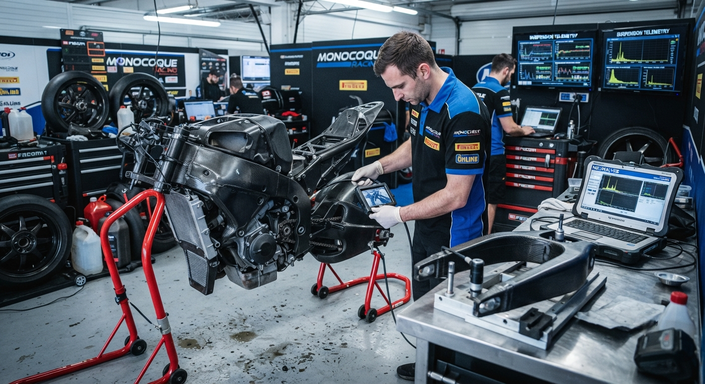
- Full Monocoque (Unibody): The frame is a single carbon fiber shell structure with integrated swingarm pivot mount, steering head, engine mounting points, and rear subframe. Used by Ducati (Desmosedici RR, Superleggera V4), BMW (HP4 Race), and several MotoGP prototypes. The monocoque achieves the highest stiffness-to-weight ratio (typically 110–150 N·mm/deg torsional rigidity at 4–7 kg frame mass for a 1,000 cc class bike) but requires the most complex mold tooling (6–12 separate mold pieces with sliding cores for internal geometry) and carries the highest manufacturing cost ($8,000–$20,000 per frame for a production run of 500 units). The layup schedule for a monocoque frame typically includes 40–50% high-modulus fiber (M40J or similar, 377 GPa modulus) in the main spars and swingarm pivot area, with 30–40% intermediate-modulus fiber (T800S, 294 GPa) in the steering head and engine mount regions, and 15–25% woven fabric in joint areas for damage tolerance. The laminate thickness ranges from 2.5–6.0 mm depending on local load intensity.
- Carbon Fiber Trellis (Space Frame): A tubular space frame constructed from carbon fiber tubes joined by metallic or composite lugs. Inspired by the traditional steel trellis frames popularized by Ducati but executed in carbon fiber tubes (typically 25–50 mm diameter, 1.5–3.0 mm wall thickness, manufactured by roll-wrapping or braiding). The tube-lug architecture allows design flexibility and reduces mold cost (only lug molds are required, not full frame molds) but typically results in 10–20% lower torsional stiffness than an equivalent monocoque at similar weight. Each tube is adhesively bonded into the lug using a structural epoxy paste adhesive with a minimum overlap length of 25–40 mm (15–20× the tube wall thickness). The joints between tubes and lugs are the critical design elements — a properly designed bonded joint in a carbon fiber trellis frame achieves 85–95% of the tube's axial strength, while a poorly designed joint can reduce strength to 30–50%.
- Semi-Monocoque (Hybrid): A hybrid architecture using a carbon fiber monocoque main structure with bolt-on aluminum or steel subframes for the rear section, engine mounts, and steering head. This approach is common in racing applications where repair and adjustability are priorities (e.g., Moto2 race frames). The carbon fiber main structure carries the primary loads, while metallic subframes handle localized attachment points and allow quick geometry changes for different track configurations. The semi-monocoque reduces mold complexity compared to a full monocoque by 30–40% and enables a 15–25% reduction in manufacturing cost, at the cost of a 3–8% weight penalty from the metallic attachments.
Swingarm Design: Structural Requirements and Laminate Optimization
The motorcycle swingarm is a cantilevered structural beam that connects the rear wheel to the frame through the pivot. It must resist bending from chain tension (3,000–6,000 N), lateral cornering forces (4,000–7,000 N), vertical bump loads (5,500–10,000 N), and combined loads during aggressive riding. The swingarm's structural performance is characterized by three key stiffness parameters: lateral bending stiffness (perpendicular to the wheel plane, critical for cornering stability), vertical bending stiffness (in the wheel plane, critical for suspension action), and torsional stiffness (about the swingarm longitudinal axis, critical for rear wheel tracking under asymmetric loading).
Carbon fiber swingarms for high-performance motorcycles are manufactured as monocoque hollow structures using bladder molding or lost-core molding. The process begins with hand layup or automated fiber placement (AFP) of prepreg plies into a two-part or multi-part mold. The layup schedule is optimized using finite element analysis to align fiber orientations with the principal stress trajectories under each load case. A typical optimized layup for a 600–1,000 cc sportbike swingarm includes approximately 45% 0° fibers (aligned along the swingarm longitudinal axis, providing vertical and lateral bending stiffness), 35% ±45° fibers (providing torsional stiffness and shear strength), and 20% 90° fibers (hoop direction, controlling cross-sectional distortion under torsion).
| Parameter | Aluminum 7075-T6 Swingarm | Carbon Fiber Monocoque Swingarm | Improvement |
|---|---|---|---|
| Mass (600–1,000 cc sportbike) | 4.8–6.5 kg | 2.2–3.5 kg | −46 to −54% |
| Lateral Bending Stiffness (kN/m) | 85–120 | 95–140 | +12 to +17% |
| Torsional Stiffness (kN·m/rad) | 8–14 | 10–18 | +25 to +29% |
| Vertical Bending Stiffness (kN/m) | 70–100 | 75–110 | +7 to +10% |
| Fatigue Life at 100% service load (cycles) | 5×10⁵ (weld-affected zone) | >10⁷ (no weld zone) | >20× |
| Manufacturing Cost (500 units/year) | $320–$520 per unit | $850–$1,600 per unit | 2.7–3.1× premium |
The chain tension and shock absorber mounting points are integrated into the swingarm structure using co-cured stainless steel or titanium inserts. The rear axle mounting area — a critical stress concentration zone — is reinforced with additional hoop layers and a co-cured aluminum or titanium insert that provides the axle bore and wheel alignment surfaces. The insert must be precisely positioned (±0.1 mm) to maintain rear wheel alignment. Most carbon fiber swingarm designs incorporate a removable chain adjustment system using a co-cured threaded insert block or a bonded aluminum eccentric adjuster plate.
Joining Methods: Metal-to-Composite Interfaces
The interface between carbon fiber structural components and metallic attachments — engine mounts, steering head bearings, swingarm pivot bearings, suspension linkage brackets — is the most failure-prone area in carbon fiber motorcycle structures. Three primary joining methods are used, each with specific performance characteristics:
- Co-cured metallic inserts: The preferred method for permanent, highly loaded connections. Metal inserts (stainless steel 17-4PH, titanium 6Al-4V, or aluminum 7075-T6) are placed in the prepreg layup before curing. The epoxy resin flows around and bonds to the insert surface during cure, producing a monolithic connection. Co-cured inserts achieve pull-out strengths of 3,500–8,000 N for M8–M12 threaded inserts in 4–8 mm laminates, with fatigue life exceeding 2×10⁶ cycles at 50% of ultimate load. The key design parameters are insert surface preparation (grit-blasted and primed with structural adhesive primer), insert geometry (at least 2.5× diameter embedment depth, with anti-rotation features such as knurling or hexagon profile), and edge distance (minimum 4× insert diameter from the laminate edge).
- Bonded metallic lugs: Used for removable components or where post-cure positioning is required. Metal lugs are bonded to cured carbon fiber surfaces using two-part structural epoxy or acrylic adhesives (typically 3M Scotch-Weld DP420, Lord 320/322, or Huntsman Araldite 2015). Bonded joints require careful surface preparation: the carbon fiber surface must be lightly abraded (180–320 grit), solvent-cleaned, and primed. The adhesive bond line thickness must be controlled at 0.10–0.25 mm using spacer beads or shims. Bonded joint strength is lower than co-cured inserts — typically achieving 60–75% of the co-cured pull-out strength — but the approach offers manufacturing flexibility and allows component replacement without replacing the entire composite structure.
- Mechanical fastening (bolted joints with inserts): Used for service-access areas such as shock absorber mounting bolts, rear axle nut, and bodywork attachment points. Bolted joints in carbon fiber require co-cured or bonded metal inserts to distribute the clamping load and prevent delamination from bolt preload. The insert size and laminate thickness at bolted joints must be designed to maintain a bearing stress below 200 MPa to avoid crushing or delamination damage under bolt preload and service loading.
Fatigue and Durability Validation
Carbon fiber motorcycle frames and swingarms must undergo extensive fatigue testing before certification for production use. The standard validation protocol, based on the ISO 15927 and manufacturer-specific test standards, includes:
- Constant amplitude fatigue testing: 1×10⁶ cycles at 0.3–1.0× maximum service load in each load case direction (vertical, lateral, longitudinal, torsional). No damage initiation (matrix cracking, delamination, or fiber failure) is permitted at 1.0× service load after 1×10⁶ cycles. At 1.3× service load, minor matrix cracking is acceptable but no delamination or fiber breakage.
- Block cycle fatigue testing: A representative race session load spectrum — typically 100 sessions of 25 minutes each — combining all load cases in the frequency distribution measured from instrumented race bikes. After the full test, the frame or swingarm must retain at least 80% of its original stiffness in each axis and must pass a static proof load test at 1.5× maximum service load.
- Environmental conditioning: Components are tested after exposure to −20°C (24 hours), +80°C at 95% relative humidity (500 hours), and salt spray per ASTM B117 (200 hours). After each environmental exposure, the component must maintain at least 90% of its baseline mechanical properties.
- Impact damage tolerance: A controlled impact (20 J, representing a tool drop or stone strike) is applied to the most vulnerable area (typically the lower spar of the swingarm or the frame down tube). After impact, the component must withstand 1.5× maximum service load in a static test and 1×10⁵ cycles at 0.5× service load without damage propagation beyond a 25 mm radius from the impact site.
Crashworthiness and Energy Absorption
One of the critical differences between carbon fiber and metallic motorcycle structures is crash behavior. Aluminum and steel frames absorb impact energy through plastic deformation — a predictable, progressive energy absorption mechanism that can be designed into the structure. Carbon fiber composites, by contrast, exhibit brittle failure with lower total energy absorption per unit mass unless specifically designed for crashworthiness. However, carbon fiber structures can be engineered for controlled energy absorption through two primary mechanisms: progressive crushing (where the composite collapses in a controlled manner from the impact initiation point, absorbing 60–90 kJ/kg of specific energy absorption (SEA)) and delamination (where controlled interlaminar separation absorbs impact energy). For motorcycle frames, crashworthiness design focuses on creating crush initiators — geometric features (chamfered edges, notches, or ply-drop sequences) at the frame's front section that trigger progressive crushing at a controlled load level (5,000–8,000 N) and maintain that crushing load during the deformation stroke. A properly designed crush initiator in a carbon fiber frame absorbs 35–55 kJ of impact energy over a 150–300 mm crush stroke — sufficient to meet the FIM (Fédération Internationale de Motocyclisme) homologation requirements for racing frames.
What is the recommended fiber orientation distribution for a carbon fiber sportbike swingarm?
For a 600–1,000 cc class sportbike swingarm, the optimized fiber orientation distribution based on multi-load-case FEA optimization is approximately 40–45% 0° fibers (aligned along the swingarm longitudinal axis), 35–40% ±45° fibers, and 15–20% 90° fibers (hoop direction). This distribution provides the optimal balance between lateral bending stiffness (dominated by 0° fibers), torsional stiffness (dominated by ±45° fibers), and cross-sectional shape retention under combined loading (dominated by 90° fibers). The specific distribution should be validated through finite element optimization for each swingarm geometry, as the optimal ratio shifts with aspect ratio — longer swingarms (560–620 mm, typical for supersport bikes) benefit from a higher 0° fiber fraction (45–50%) to control bending deflection, while shorter swingarms (500–550 mm, typical for supernaked and streetfighter bikes) can tolerate a higher ±45° fraction (40–45%) for improved torsional response. The ply transition between different orientation zones should be gradual, with no more than 4 consecutive plies of the same orientation to prevent matrix-dominated failure modes.
How does a carbon fiber monocoque frame compare to aluminum twin-spar in terms of rider feedback and flex characteristics?
Carbon fiber monocoque frames exhibit fundamentally different flex characteristics compared to aluminum twin-spar frames due to the anisotropic nature of the composite material. Aluminum frames have isotropic flex behavior — the stiffness in each direction is determined purely by the geometry and wall thickness. Carbon fiber monocoque frames, by contrast, can be engineered to have directionally specific stiffness: high torsional rigidity (for stability under hard braking and cornering) combined with carefully controlled lateral compliance (for rider feedback and traction feel). This directional stiffness tuning — impossible with metallic construction — is one of the primary performance advantages of carbon fiber frames. MotoGP carbon fiber frames typically achieve torsional rigidity of 130–150 N·mm/deg and lateral bending stiffness of 45–70 N/mm, compared to an aluminum twin-spar frame's 80–110 N·mm/deg torsional and 60–90 N/mm lateral. The carbon fiber frame thus provides 30–50% higher torsional stiffness while being 25–35% more compliant laterally, producing a flex character that experienced riders describe as more communicative and confidence-inspiring at extreme lean angles. The specific flex profile can be tuned by adjusting the ply schedule — for example, adding ±45° plies in the main spar increases torsional stiffness without significantly affecting lateral bending, while adding 0° plies in the lower spar increases both lateral and vertical stiffness simultaneously.
What inspection methods are used to detect damage in carbon fiber motorcycle frames and swingarms?
Four primary non-destructive inspection (NDI) methods are used for carbon fiber motorcycle structures, each with different detection capabilities. (1) Visual inspection with dye penetrant: Effective for detecting surface cracks, impact marks, and gel coat damage. The frame is sprayed with a fluorescent dye penetrant, allowed to dwell for 10–30 minutes, excess dye is removed, and developer is applied. Under UV light, crack indications as small as 0.1 mm width are visible. This is the primary inspection method used by race teams between sessions. (2) Tap testing (coin tap or automated tap hammer): A trained technician taps the carbon fiber surface with a light hammer or coin and listens for the characteristic sound — a sharp, high-pitched ring indicates sound laminate, while a dull, low-pitched thud indicates delamination or disbond. This method detects subsurface damage 5–30 mm below the surface but requires operator experience and is qualitative rather than quantitative. (3) Ultrasonic testing (A-scan or C-scan): Pulse-echo or through-transmission ultrasound at 1–10 MHz frequency detects delamination, voids, and disbonds with 80–95% probability of detection for defects >5 mm diameter. C-scan provides a planar map of damage, which is useful for quantifying the extent of impact damage. (4) Thermography (active or passive): An infrared camera detects surface temperature differences caused by subsurface flaws. Active thermography (using a flash lamp or hot air pulse to heat the surface) can detect delamination at depths of 2–6 mm in carbon fiber laminates. Passive thermography (monitoring the component during operation) can detect developing damage from friction or microcracking. For racing applications, a combination of visual inspection (pre-session), tap testing (post-session), and periodic ultrasonic or thermographic inspection (every 50–100 race hours) is the recommended NDI protocol.
Conclusion
Carbon fiber motorcycle frames and swingarms represent the state of the art in structural composite design for powersports applications, delivering 35–55% weight reduction over equivalent aluminum structures while providing superior directional stiffness tuning, fatigue performance exceeding 10⁷ cycles, and energy absorption capability of 35–55 kJ through controlled crushing. The three primary architecture choices — full monocoque, carbon fiber trellis, and semi-monocoque hybrid — offer different trade-offs between weight, stiffness, manufacturing cost, and serviceability. For B2B buyers, the key technical decisions in carbon fiber frame and swingarm procurement are the selection of fiber modulus grade (standard vs. intermediate vs. high modulus), the joining method for metallic interfaces (co-cured inserts for permanent connections, bonded lugs for removable components, mechanical fasteners for service points), and the validation protocol for fatigue and crashworthiness certification. As electric hyperbikes such as the Lightning LS-218, Energica Ego, and LiveWire S2 continue to push power-to-weight boundaries, the demand for carbon fiber structural components in the motorcycle industry is expected to accelerate, with the carbon fiber content per premium motorcycle projected to increase from the current 8–15 kg to 15–25 kg by 2030.
Part of topic
Related Articles
- Carbon Fiber Mooring for Floating Offshore Wind: Fatigue and Corrosion in Deep Water
- Carbon Fiber Bicycle Frame Optimization: Layup Design and Manufacturing for Competitive Racing
- Carbon Fiber CFRP Retrofit for Infrastructure: Bridge and Building Seismic Strengthening
- Carbon Fiber Medical Imaging Equipment: Lightweight Gantry and Couch Structures for MRI/CT
- Carbon Fiber EV Battery Enclosures: Crash Safety and Electromagnetic Shielding Design
- Carbon Fiber Structures for Low-Altitude Economy: UAV Airframes and eVTOL Components
Interested in Our Products?
Contact our team for competitive pricing and technical specifications.
Get a QuoteRelated Products

Carbon fiber standard plate-3k stripe
Lightweight, ultra-rigid standard sheets for drone fuselages, robot housings, facades and structural applications.

Square Carbon Fiber Tube — 3K Twill T700
Square cross-section carbon fiber tube manufactured with 3K twill weave for torsional strength. Preferred for structural frames, trusses, and support columns where rectangular geometry offers design flexibility.

Carbon Fiber Plate — 3K Twill T700 3.0mm
Medium-thickness 3.0mm carbon fiber plate offering significantly higher load capacity while maintaining attractive 3K twill finish. Suitable for structural brackets, reinforcement plates, and load-bearing panels.

Carbon Fiber Plate — 3K Twill T700 1.5mm
Thin 1.5mm carbon fiber plate with 3K twill weave surface. Lightweight and stiff, commonly used for covers, panels, drone bodies, and applications requiring a premium aesthetic appearance.

Carbon Fiber Plate — UD Unidirectional T700
Unidirectional carbon fiber plate with all fibers oriented in a single direction for maximum strength along the fiber axis. Essential for structural reinforcements, splints, and applications where load direction is predictable.