
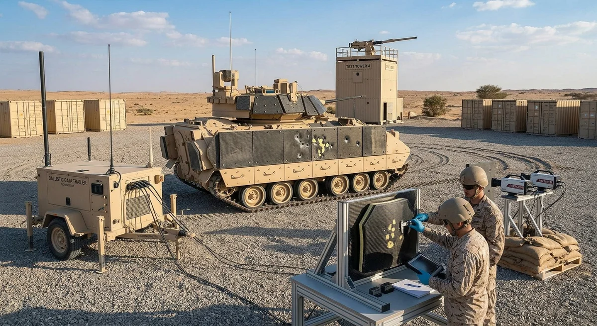
Carbon fiber composites are revolutionizing military vehicle design by reducing weight while maintaining ballistic protection. This article examines armor solutions, structural applications, and cost-benefit analysis for armored personnel carriers, main battle tanks, and tactical trucks, with comparison data for B2B defense industry buyers.
Modern military ground vehicles face an increasingly difficult design paradox: they must provide ever-higher levels of ballistic and blast protection, yet remain mobile enough for rapid deployment and tactical maneuverability. Carbon fiber composites offer a transformative solution, enabling weight reductions of 30-50% compared to traditional steel armor and 15-25% compared to aluminum armor, while meeting or exceeding military ballistic protection standards. The global market for military vehicle armor composites is projected to reach $4.2 billion by 2032, with carbon fiber-based solutions representing the fastest-growing segment at 12.8% CAGR.
Defense programs worldwide are integrating carbon fiber composites into vehicle structures — from the US Army's Optionally Manned Fighting Vehicle (OMFV) program to the UK's Ajax, Germany's Puma IFV, and China's VN17 infantry fighting vehicles. This article provides B2B buyers in the defense supply chain with detailed technical data on carbon fiber armor solutions, structural applications, and deployment considerations.
Ballistic Protection Performance
Carbon fiber composite armor systems must defeat a range of threats specified by military standards. The primary ballistic standards governing vehicle armor include:
| Standard | Country/Region | Threat Level | Typical Projectile | Required Areal Density |
|---|---|---|---|---|
| STANAG 4569 Level III | NATO | 7.62×51 mm AP (M993) | 8.4 g tungsten carbide core at 930 m/s | 35-50 kg/m² (steel); 22-35 kg/m² (CFRP/ceramic) |
| STANAG 4569 Level IV | NATO | 14.5×114 mm AP (B32) | 64 g steel core at 890 m/s | 80-120 kg/m² (steel); 50-80 kg/m² (CFRP/ceramic) |
| STANAG 4569 Level V | NATO | 25 mm APDS-T (M791) | 135 g tungsten core at 1,390 m/s | 150-200 kg/m² (composite) |
| GOST R 50963-96 Level 6a | Russia | 7.62×54R AP (B-32) | 10.4 g steel core at 830 m/s | 40-55 kg/m² (steel) |
| NIJ 0108.01 Level III | USA (vehicle) | 7.62×51 mm AP (M2 AP) | 10.8 g steel core at 870 m/s | 30-45 kg/m² (CFRP/ceramic) |
| GJB 59.18-88 Level 3 | China | 12.7×108 mm AP (DJB-023) | 48.5 g steel core at 820 m/s | 65-90 kg/m² (composite) |
Carbon Fiber Armor Architecture
Modern carbon fiber composite armor systems use layered constructions that combine multiple materials for optimized performance. The most common architectures include:
- Ceramic-faced CFRP (Al₂O₃/SiC + carbon fiber): Alumina or silicon carbide tiles (6-15 mm thick) bonded to a carbon fiber composite backing plate (10-20 mm). The ceramic erodes and fractures the projectile tip, while the carbon fiber backing captures fragments and distributes load. Weight saving: 35-50% vs. steel at STANAG Level IV.
- Spectra Shield + CFRP hybrid: Ultra-high-molecular-weight polyethylene (UHMWPE) layers stacked with carbon fiber skins. UHMWPE provides excellent multi-hit performance against fragmenting threats; carbon fiber adds stiffness and structural integrity. Used in thin armor applications requiring 20-30 mm total thickness.
- CFRP-metal laminate (CFRP + titanium/aluminum): Alternating layers of carbon fiber prepreg (0.5-1.0 mm per ply) and thin metal sheets (0.3-1.0 mm). Titanium offers the best corrosion resistance and high-temperature performance; aluminum offers cost advantages. Stack sequence: 5-20 layers depending on threat level.
- Reactive armor with CFRP spall liner: Explosive reactive armor (ERA) tiles mounted on a carbon fiber composite spall liner. The CFRP liner (5-10 mm) contains fragmentation from both the ERA explosion and the impacting projectile, preventing interior spallation.
| Armor Configuration | Threat Stopped | Areal Density (kg/m²) | Weight vs. Steel | Cost Multiplier vs. Steel | TRL |
|---|---|---|---|---|---|
| RHA steel (baseline) | STANAG IV | 80-120 | 1.0× (baseline) | 1.0× | 9 |
| Aluminum 7039 | STANAG III | 42-55 | 0.55× | 1.5-2.0× | 9 |
| Al₂O₃ + CFRP backing | STANAG IV | 50-80 | 0.60-0.65× | 3-5× | 8 |
| SiC + CFRP backing | STANAG IV | 45-70 | 0.55-0.58× | 5-8× | 7 |
| SiC + titanium + CFRP laminate | STANAG V | 100-150 | 0.65-0.75× | 8-12× | 6 |
| B₄C + UHMWPE + CFRP hybrid | STANAG IV | 38-55 | 0.45-0.50× | 6-10× | 7 |
Structural Applications Beyond Armor
Beyond ballistic protection, carbon fiber composites are increasingly used for structural components where weight reduction directly translates to improved payload, range, or mobility:
- Vehicle hull and monocoque structures: Full carbon fiber monocoque hulls for light armored vehicles (6-12 tons class). The US Army's Advanced Armored Vehicle concept uses a CFRP monocoque that saves 35% weight versus aluminum. AFP (automated fiber placement) manufacturing enables complex curved geometries with localized reinforcement. Production cost premium: 20-30% per hull, offset by 25-40% range improvement.
- Suspension arms and control arms: Replace forged aluminum components. Weight reduction: 40-60% per component. Fatigue life: >10,000 cycles at 80% of yield load. Applications include tracked vehicle road-arm assemblies and tactical truck control arms. Combat-proven: used in the German Puma IFV suspension system.
- Weapon station components: Remote weapon station (RWS) mounts, ammunition handling systems, and gun shields. Weight reduction enables higher payload capacity for sensors and ammunition. Example: CFRP RWS mount saves 45 kg (35% weight reduction) compared to steel.
- Road wheels and idler wheels: For tracked vehicles, CFRP road wheels reduce unsprung mass by 45-55%, improving ride quality and track life. A 6-wheel set for a 30-ton IFV saves approximately 120 kg. Field trials by the US Army show 30% longer track life with CFRP road wheels.
- Fuel and water tanks: Filament-wound CFRP tanks (using polyphenylene sulfide or PEEK matrix for chemical resistance). Weight reduction: 50-70% vs. steel. Ballistic self-sealing: CFRP tanks have demonstrated self-sealing capability after 7.62 mm AP hits at -40°C to +60°C.
- Mine blast energy absorbers: Core CFRP sandwich structures (carbon fiber skins with foam or aluminum honeycomb core) placed between the vehicle floor and hull. Absorb 60-80% of blast energy from 6-10 kg TNT equivalent underfloor mine blasts. Survives NATO AEP-55 Level 3a/b mine blast testing.
Case Study: CFRP Armor Upgrade for Tactical Wheeled Vehicles
| Parameter | Steel Armor (Baseline) | CFRP Composite Upgrade | Improvement |
|---|---|---|---|
| Vehicle curb weight (5-ton truck) | 7,500 kg | 6,100 kg | -18.7% |
| Armor package weight | 1,800 kg | 850 kg | -52.8% |
| Payload capacity | 2,500 kg | 3,900 kg | +56% |
| Ballistic protection level | STANAG III (7.62×51 AP) | STANAG III+ (12.7×10⁸ AP, front arc) | Enhanced |
| Operational range (on-road) | 600 km | 720 km | +20% |
| Armor system cost | $45,000 | $185,000 | 4.1× |
| Total lifetime cost (20 years) | $1.2M | $1.35M | +12.5% (lower fuel) |
| Aircraft C-130 transportable | 2 vehicles per mission | 3 vehicles per mission | +50% deployment |
Manufacturing and Integration Challenges
Military vehicle applications present unique manufacturing requirements that differ from aerospace or automotive composites:
- Environmental durability: Military vehicles operate across extreme temperature ranges (-46°C to +71°C for US MIL-STD-810), in high humidity, salt spray, sand, and chemical agent environments. Resin systems must maintain mechanical properties across this range. Epoxy formulations qualified to MIL-DTL-64154 and MIL-DTL-46100 are commonly specified. Polybenzimidazole (PBI) and polyimide matrices offer extended temperature capability.
- Ballistic testing and qualification: Full-scale ballistic testing of armor panels requires certified test ranges. V50 ballistic limit testing (MIL-STD-662F) determines the velocity at which 50% of projectiles are stopped. Typical qualification: minimum 5 panels per threat level, 8-12 shots per panel, with statistical analysis per MIL-DTL-46100.
- Repair in the field: Battle damage repair procedures for CFRP structures use pre-cured patch kits with two-part epoxy adhesives. A typical 300×300 mm patch repair takes 2-4 hours at 20°C (field temperature). Barrier materials for heat-cured systems: silicone heater blankets powered by vehicle electrical system (24-28 VDC).
- EMI/RFI shielding: Carbon fiber is electrically conductive (resistivity: 1.5×10⁻³ Ω·cm), providing inherent EMI shielding effectiveness of 30-50 dB in the 1-18 GHz range. Additional shielding (to 60-80 dB for military vehicle TEMPEST requirements) can be achieved with copper mesh interlayers or conductive surface coatings.
Supply Chain and Procurement for Defense Buyers
Defense procurement of carbon fiber armor components requires careful attention to material sourcing, certification, and ITAR compliance:
- Material certification: All composite armor materials must be procured with certified material traceability per MIL-HDBK-17 (now CMH-17) or equivalent national standards. PAN carbon fibers for defense applications typically require MIL-DTL-46100 or A-A-59383 certification.
- Qualified manufacturers: Key suppliers include Morgan Advanced Materials, Ceradyne (3M), CoorsTek (for ceramic armor), Hexcel, Toray Advanced Composites, and Gurit for defense-grade CFRP materials.
- ITAR/EAR compliance: Carbon fiber armor composites with specific ballistic performance characteristics and their manufacturing equipment may be subject to US ITAR (22 CFR 120-130) or EU dual-use export controls (EU Regulation 428/2009). Buyers should verify export classification with suppliers.
- Lead times: Typical lead times for defense-grade CFRP armor panels: 12-20 weeks from order to delivery, including material procurement, layup, cure (autoclave or press), ballistic testing (NDT + sample destructive), and certification documentation.
FAQ
Can carbon fiber armor stop a direct hit from a 7.62×51 mm armor-piercing round?
Yes, when configured as part of a ceramic-faced composite armor system. A 10-12 mm thick silicon carbide (SiC) or boron carbide (B₄C) ceramic tile bonded to a 12-16 mm carbon fiber/epoxy backing plate reliably stops 7.62×51 mm AP M993 ammunition at muzzle velocity (930 m/s). The ceramic breaks up the tungsten carbide penetrator, and the carbon fiber backing captures the fragments and ceramic debris. This configuration achieves areal density of 30-40 kg/m² — approximately 40-50% lighter than the equivalent rolled homogeneous armor (RHA) steel that would require 20-25 mm thickness (160-200 kg/m²). Multi-hit capability typically requires 100-150 mm spacing between impact points for ceramic-faced systems to avoid adjacent tile fracture.What are the main cost barriers to widespread adoption of carbon fiber armor in military vehicles?
The primary cost barriers are material cost (defense-grade PAN carbon fiber prepreg at $50-120/kg vs. $2-5/kg for armor steel), ceramic tile manufacturing cost (SiC tiles at $200-800/m²), and autoclave curing (high capital and cycle time costs). Current armoring cost is $3,000-8,000/m² for ceramic-CFRP armor vs. $500-1,500/m² for steel armor. However, system-level total cost of ownership (TCO) analysis shows that the weight savings fuel reduction over a 20-year vehicle life offsets 30-50% of the upfront cost premium. Emerging technologies — out-of-autoclave (OOA) prepregs, rapid press-curing, and automated fiber placement (AFP) for armor layups — are expected to reduce manufacturing cost by 30-40% by 2028-2030.How does carbon fiber armor perform in extreme cold (-40°C) conditions?
Carbon fiber composites retain their mechanical properties well at low temperatures. At -40°C, carbon fiber/epoxy composites typically show 5-15% increase in tensile strength and modulus compared to room temperature, due to the epoxy matrix becoming stiffer. The coefficient of thermal expansion (CTE) of CFRP is near-zero (approximately 0.5-1.5×10⁻⁶/°C in the fiber direction), which minimizes thermal stress in armor assemblies. However, the epoxy matrix becomes more brittle at low temperature, reducing fracture toughness by 10-30%. Ceramic-CFRP armor systems have been qualified per MIL-STD-810G Method 503.5 (low temperature) for operation at -46°C without brittle failure. For extreme cold applications, toughened epoxy formulations or thermoplastic matrices (PEEK, PEKK) are recommended. UHMWPE hybrid layers (Spectra/Dyneema) can experience reduced ballistic performance below -30°C and should be tested for specific temperature requirements.Part of topic
Related Articles
- Carbon Fiber Mooring for Floating Offshore Wind: Fatigue and Corrosion in Deep Water
- Carbon Fiber Bicycle Frame Optimization: Layup Design and Manufacturing for Competitive Racing
- Carbon Fiber CFRP Retrofit for Infrastructure: Bridge and Building Seismic Strengthening
- Carbon Fiber Medical Imaging Equipment: Lightweight Gantry and Couch Structures for MRI/CT
- Carbon Fiber EV Battery Enclosures: Crash Safety and Electromagnetic Shielding Design
- Carbon Fiber Structures for Low-Altitude Economy: UAV Airframes and eVTOL Components
Interested in Our Products?
Contact our team for competitive pricing and technical specifications.
Get a QuoteRelated Products

Carbon Fiber Plate — 3K Twill T700 1.5mm
Thin 1.5mm carbon fiber plate with 3K twill weave surface. Lightweight and stiff, commonly used for covers, panels, drone bodies, and applications requiring a premium aesthetic appearance.

Carbon fiber standard plate-3k stripe
Lightweight, ultra-rigid standard sheets for drone fuselages, robot housings, facades and structural applications.

Square Carbon Fiber Tube — 3K Twill T700
Square cross-section carbon fiber tube manufactured with 3K twill weave for torsional strength. Preferred for structural frames, trusses, and support columns where rectangular geometry offers design flexibility.

Carbon Fiber Plate — 3K Twill T700 3.0mm
Medium-thickness 3.0mm carbon fiber plate offering significantly higher load capacity while maintaining attractive 3K twill finish. Suitable for structural brackets, reinforcement plates, and load-bearing panels.

Carbon Fiber Plate — UD Unidirectional T700
Unidirectional carbon fiber plate with all fibers oriented in a single direction for maximum strength along the fiber axis. Essential for structural reinforcements, splints, and applications where load direction is predictable.