
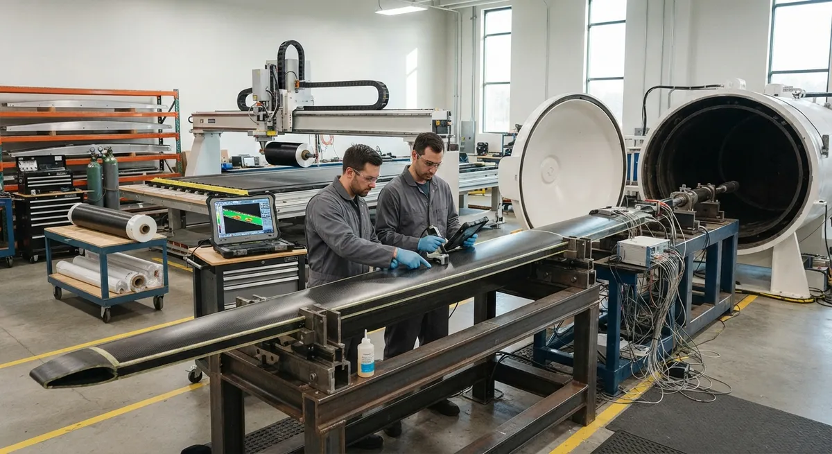
The carbon fiber UAV wing spar is the most important structural member in a military drone. It carries the bending moment from lift and high-G maneuvers and sets the stiffness, mass, and fatigue life of the entire wing. A spar too heavy steals payload; one too flexible degrades control;
Introduction
The carbon fiber UAV wing spar is the most important structural member in a military drone. It carries the bending moment from lift and high-G maneuvers and sets the stiffness, mass, and fatigue life of the entire wing. A spar too heavy steals payload; one too flexible degrades control; one too stiff fails without warning.
For military platforms the envelope is unforgiving: 6-9g maneuvers, gust loads, thermal cycling, and, on stealth aircraft, near-invisibility to radar. This article covers how composite spars are architected, laminated, manufactured, and qualified for those demands.
High-G Maneuver Loads and Spar Architecture
Military UAVs typically design to limit load factors of 6-9g, with ultimate factors of 1.5 times limit. For a 600 kg class drone, a 7g pull produces roughly 41 kN of lift, absorbed at the wing-root cap as several hundred kN·m of bending moment. Loading is dynamic, so fatigue and damage tolerance are designed in from the start.
Three cross-section families dominate:
- I-beam spar: the highest bending efficiency per kilogram, with caps resisting tension and compression and a thin web carrying shear; the classic choice for high-aspect-ratio wings.
- C-channel spar: easier to co-cure with skins and ribs and simpler to inspect, at the cost of lower bending efficiency; common on smaller tactical drones.
- Box spar: a closed torsion box of two caps and two webs resisting bending and twist; preferred on delta-wing and tailless UCAV layouts.
On high-G platforms, I-beam or box spars with continuous cap plies are standard.
Spar Cap Design with Unidirectional Carbon Fiber
The spar cap is the strength-critical zone, built from unidirectional (UD) carbon fiber prepreg oriented near the spanwise axis, because UD material develops the highest modulus and strength in the fiber direction. The table below compares the fibers most often specified for spar caps with 7075-T6 aluminum.
| Fiber / material | Tensile strength (GPa) | Tensile modulus (GPa) | Density (g/cm³) |
|---|---|---|---|
| T700S carbon, UD prepreg | 4.9 | 230 | 1.60 |
| T800S carbon, UD prepreg | 5.9 | 294 | 1.60 |
| Intermediate modulus (IM) carbon | 6.3-7.0 | 290-300 | 1.58 |
| Aluminum 7075-T6 (reference) | 0.572 (yield 0.503) | 71.7 | 2.81 |
A typical cap stack runs at 60-70% fiber volume fraction, with 40% or more of the plies at 0° and ±45° plies at the edges for load introduction and delamination resistance. Dropping plies toward the wingtip trims weight where the bending moment falls. Coupon tests per ASTM D3039 and ASTM D7264 validate the allowables.
Load Path and Stealth Structure Integration
The spar does not act alone. Load runs from the skin through the ribs into the spar, then into the wing-fuselage lugs. The rib-to-spar interface is bonded and mechanically fastened, with shear through the web and axial loads through the caps, and ply drops keep the load path smooth and void-free.
On stealth UCAVs the spar must also stay invisible to radar and coexist with avionics:
- Radar signature: carbon fiber is conductive and reflective at radar frequencies, so radar-absorbent material (RAM) coatings are applied and internal structure avoids long reflective channels.
- EMI and lightning: carbon fiber conducts roughly 1000 times worse than aluminum, so spars need lightning protection and bond paths; expanded copper foil is co-cured into the skin and conductive fasteners bridge joints.
- Antenna integration: an antenna under a conductive skin is shielded. Antenna zones sit in non-conductive radome windows, and the spar is routed around them with structural inserts so the load path bends cleanly.
These requirements become part of the structural drawing, and signature testing runs alongside structural tests.
Manufacturing Methods
Three processes dominate spar production:
- Prepreg autoclave: the workhorse for primary structure. UD prepreg cures under 6-7 bar at 120-180 °C, giving porosity below 1% and the highest mechanical performance, at the highest cost.
- Automated fiber placement (AFP): robotically placed tows enable ply drops and net-shape caps with low scrap, preferred for long spars and variable-thickness caps.
- Out-of-autoclave (OOA): vacuum-bag-only prepreg systems cure in an oven, cutting capital cost; parts reach 1-2% porosity, adequate for many secondary and some primary structures.
Tooling matters as much: matched carbon tooling controls the final thickness and twist of a long spar.
Weight, Fatigue, and Cost vs Aluminum Spars
| Parameter | Aluminum 7075 spar | Carbon fiber spar |
|---|---|---|
| Density (g/cm³) | 2.81 | 1.60 |
| Specific strength (strength/density, km) | 20.4 | 306-437 (T700S-T800S) |
| Specific modulus (modulus/density, ×10⁶ m) | 2.55 | 14.4-18.4 |
| Spar mass, 6 m wing (reference) | Baseline | Reduced 25-40% |
| Fatigue under spectrum loading | Crack-initiation limited, finite life | Near-infinite in 0° direction, damage-tolerant |
A 20-40% reduction in spar mass converts directly into payload, endurance, or fuel. Fatigue differs: metals fail from crack growth, composites from progressive damage such as delamination and fiber breakage, usually triggered by impact. A 35 J impact can cut compression strength by 50%, so spars carry a compression-after-impact margin sized for several design lifetimes.
Cost is the trade. Prepreg dominates material cost at scale, so net-shape AFP layup and co-curing cut scrap, while OOA trades a small porosity penalty for a lower capital barrier. Locking the material system early and reusing the spar design across variants amortizes qualification cost, which is why programs from MQ-9-class reconnaissance aircraft to Bayraktar-style tactical drones specify carbon spars.
Quality Control and Certification
Composites can hide defects metals cannot, so non-destructive testing (NDT) is mandatory for a flight-critical spar:
- Ultrasonic inspection (pulse-echo or phased array) maps delaminations, porosity, and fiber wrinkles across the spar, with porosity limits below 1% for autoclave structure and 1-2% for OOA parts.
- X-ray computed tomography (CT) resolves joint and ply-drop interiors.
- Thermography and shearography screen bonded joints in production.
- Material qualification runs lot-based testing, with design allowables at B-basis (95% confidence, 90% survival).
Every spar receives an ultrasonic C-scan record tied to its serial number, backed by coupons from the same cure batch; that traceability is what defense customers audit.
Frequently Asked Questions
Why is unidirectional carbon fiber used for spar caps?
Unidirectional plies concentrate fiber along the spanwise axis for the highest strength and stiffness per kilogram: T700S delivers 4.9 GPa tensile strength and 230 GPa modulus; T800S reaches 5.9 GPa and 294 GPa. Angle plies at the edges handle load introduction and shear.
How much weight does a carbon fiber spar save versus aluminum?
Typically 20-40% on the spar itself. Carbon composite at 1.60 g/cm³ replaces 7075 aluminum at 2.81 g/cm³ with roughly five times the specific strength, so the saved mass converts directly into payload, endurance, or fuel.
Which NDT methods are used to certify a composite wing spar?
Ultrasonic C-scan (pulse-echo or phased array) is the standard full-field method, mapping porosity and delamination with limits below 1% for autoclave structure. X-ray CT resolves joint and ply-drop interiors, and thermography or shearography screen bonded joints in production.
Conclusion
The wing spar is where the biggest performance decisions on a military drone are made. High-G loads are carried by UD cap laminates that beat aluminum on every specific-strength metric, spar architecture manages load path and torsion, and stealth requirements fold radar, EMI, and antenna integration into the structural layout. Autoclave prepreg, AFP, and OOA each trade cost against porosity, and every spar is qualified by NDT and coupon testing before its first flight.
For UAV manufacturers, defense tier suppliers, and composite engineers specifying spar laminates, material consistency and property traceability are the foundation of the whole program. Explore our aerospace-grade carbon fiber range, including unidirectional and prepreg materials with controlled fiber volume fraction, or contact our engineering team to discuss spar laminate design for your platform.
Part of topic
Related Articles
- Carbon Fiber Mooring for Floating Offshore Wind: Fatigue and Corrosion in Deep Water
- Carbon Fiber Bicycle Frame Optimization: Layup Design and Manufacturing for Competitive Racing
- Carbon Fiber CFRP Retrofit for Infrastructure: Bridge and Building Seismic Strengthening
- Carbon Fiber Medical Imaging Equipment: Lightweight Gantry and Couch Structures for MRI/CT
- Carbon Fiber EV Battery Enclosures: Crash Safety and Electromagnetic Shielding Design
- Carbon Fiber Structures for Low-Altitude Economy: UAV Airframes and eVTOL Components
Interested in Our Products?
Contact our team for competitive pricing and technical specifications.
Get a QuoteRelated Products

Carbon fiber standard plate-3k stripe
Lightweight, ultra-rigid standard sheets for drone fuselages, robot housings, facades and structural applications.

Carbon Fiber Plate — 3K Twill T700 3.0mm
Medium-thickness 3.0mm carbon fiber plate offering significantly higher load capacity while maintaining attractive 3K twill finish. Suitable for structural brackets, reinforcement plates, and load-bearing panels.

Carbon Fiber Plate — 3K Twill T700 1.5mm
Thin 1.5mm carbon fiber plate with 3K twill weave surface. Lightweight and stiff, commonly used for covers, panels, drone bodies, and applications requiring a premium aesthetic appearance.

Square Carbon Fiber Tube — 3K Twill T700
Square cross-section carbon fiber tube manufactured with 3K twill weave for torsional strength. Preferred for structural frames, trusses, and support columns where rectangular geometry offers design flexibility.

Carbon Fiber Plate — UD Unidirectional T700
Unidirectional carbon fiber plate with all fibers oriented in a single direction for maximum strength along the fiber axis. Essential for structural reinforcements, splints, and applications where load direction is predictable.