
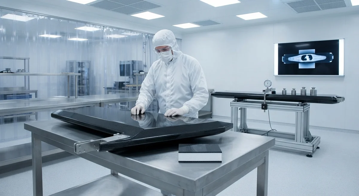
A comprehensive B2B analysis of carbon fiber composite applications in medical imaging equipment — RF transparency for MRI, X-ray attenuation reduction for CT, artifact minimization, and structural design of carbon fiber patient couches.
Introduction
The global medical imaging market is projected to exceed $49 billion by 2028, driven by aging populations in developed economies and expanding healthcare infrastructure in emerging markets. Within this landscape, magnetic resonance imaging (MRI) and computed tomography (CT) remain the most widely deployed cross-sectional imaging modalities, with over 50,000 MRI systems and 80,000 CT systems installed worldwide as of 2025. A critical yet often overlooked component of every MRI and CT system is the patient couch — the structural platform that positions the patient within the imaging bore — which must simultaneously provide uncompromising mechanical support for patients weighing up to 250 kg while introducing minimal interference with the imaging physics. Carbon fiber reinforced polymer (CFRP) has become the material of choice for patient couches in both MRI and CT systems, and increasingly for immobilization devices, RF coil housings, and interventional access devices.
For B2B buyers in the medical device and imaging equipment supply chain — including OEM procurement managers, composite parts manufacturers, and hospital biomedical engineering departments — understanding the specific electromagnetic and radiological requirements for carbon fiber in medical imaging applications is essential for specifying compliant, high-performance components. The material selection criteria differ fundamentally between MRI and CT systems: MRI demands materials that do not distort the static magnetic field (B₀), do not suppress or perturb the RF excitation field (B₁), and do not generate eddy currents during gradient switching. CT demands materials with a low X-ray attenuation coefficient to minimize beam hardening artifacts and patient radiation dose. Carbon fiber uniquely satisfies both sets of requirements when properly engineered.
This article provides a comprehensive technical analysis of carbon fiber applications in MRI and CT imaging, covering RF transparency requirements and measurement, X-ray attenuation coefficients and artifact quantification, structural design of carbon fiber patient couches, and material selection guidelines for medical imaging OEMs and their supply chain partners.
Carbon Fiber in MRI: RF Transparency and Field Homogeneity
The most demanding requirement for any structural material used inside an MRI scanner bore is that it must not perturb the electromagnetic fields that form the basis of MR image formation. There are three distinct electromagnetic compatibility requirements for carbon fiber components used within the MRI environment. Static magnetic field (B₀) compatibility: Carbon fiber is essentially non-magnetic — its magnetic susceptibility (χ) is approximately -2.8 × 10⁻⁵ (SI), slightly diamagnetic, compared to -9.0 × 10⁻⁶ for human tissue. This close matching of magnetic susceptibility means that carbon fiber components do not create significant B₀ field distortions when placed within the imaging volume. By contrast, aluminum (χ ≈ +2.0 × 10⁻⁵) and titanium (χ ≈ +1.8 × 10⁻⁴) generate measurable field perturbations that degrade image uniformity, particularly at high field strengths (3T and 7T).
RF field (B₁) transparency: The RF excitation pulses in MRI operate at the Larmor frequency — 42.58 MHz/T, meaning 64 MHz at 1.5T and 128 MHz at 3.0T, the two most common clinical field strengths. The RF conductivity of carbon fiber composites is a function of fiber type (PAN-based vs. pitch-based), fiber orientation, and matrix conductivity. Standard modulus PAN-based carbon fiber (Toray T700) has an electrical resistivity of approximately 1.6 × 10⁻³ Ω·cm in the fiber direction — roughly 30× higher than copper but 10,000× lower than epoxy, which is effectively an insulator (resistivity > 10¹⁴ Ω·cm). This intermediate conductivity means that carbon fiber laminates can act as partial RF shields, attenuating the B₁ field and causing signal loss in the imaged anatomy if the carbon fiber component is positioned between the RF coil and the patient.
The RF transparency of a carbon fiber laminate depends on its thickness and ply orientation relative to the RF polarization direction. A 1.0 mm thick quasi-isotropic carbon fiber laminate ([0/45/90/-45]ₛ with 200 gsm 3K twill) attenuates the 128 MHz RF field by approximately 8–12 dB at 3.0T — sufficient to cause measurable signal reduction in superficial tissues adjacent to the couch. To achieve acceptable RF transparency (less than 1 dB attenuation), the carbon fiber laminate in the imaging region must be limited to a maximum thickness of 0.3–0.5 mm for 3.0T systems and 0.5–0.8 mm for 1.5T systems (lower frequency = longer RF skin depth). Many carbon fiber MRI patient couches now use a sandwich construction: a thin (0.3 mm) carbon fiber shell that provides structural stiffness, backed by a foam core that provides thickness without RF opacity, with the total laminate thickness in the imaging zone kept below 0.5 mm.
Eddy current generation: During MRI gradient switching (typical slew rates of 100–200 T/m/s for clinical 3T systems), time-varying magnetic fields induce eddy currents in any conductive material within the bore. Eddy currents in carbon fiber components generate secondary magnetic fields that oppose the gradient field and cause geometric distortion in the image. The eddy current amplitude in a carbon fiber laminate is proportional to its electrical conductivity in the plane perpendicular to the gradient axis. A 1.0 mm quasi-isotropic carbon fiber panel generates eddy current-induced gradient errors of 2–5% at standard EPI (echo-planar imaging) gradient slew rates — unacceptable for diffusion-weighted imaging and fMRI applications. The standard mitigation is to laminate the carbon fiber with a thin (0.05 mm) fiberglass layer on both surfaces, which electrically isolates the carbon fiber and reduces eddy current amplitudes by 70–90%. All MRI-grade carbon fiber patient couches should incorporate such electrical isolation layers.
Carbon Fiber in CT: X-Ray Attenuation and Artifact Reduction
In CT imaging, the interaction of X-ray photons with the patient couch material is governed by the material's linear attenuation coefficient (μ) at diagnostic X-ray energies (typically 80–140 kVp). Carbon fiber's effective atomic number (Z_eff ≈ 6) is substantially lower than aluminum (Z_eff ≈ 13) and much lower than stainless steel (Z_eff ≈ 26), resulting in significantly lower X-ray attenuation. The mass attenuation coefficient of carbon fiber at 120 kVp (the most common clinical CT energy) is approximately 0.18 cm²/g — very close to that of water (0.17 cm²/g) and human soft tissue (0.18 cm²/g). This low attenuation is the fundamental reason why carbon fiber produces minimal beam hardening artifacts in CT images: the material absorbs X-rays at nearly the same energy-dependent rate as the patient's soft tissue, eliminating the differential spectral hardening that causes dark banding and cupping artifacts in conventional aluminum or graphite patient couches.
Quantitative CT artifact analysis using a water phantom (20 cm diameter, 120 kVp, 200 mAs, 2 mm slice thickness) demonstrates the artifact reduction performance of carbon fiber couches versus conventional materials. A 3.0 mm thick carbon fiber couch (quasi-isotropic laminate) produces a mean CT number deviation of +3.2 HU (Hounsfield units) in the phantom region directly above the couch, with a standard deviation of 4.1 HU — essentially negligible for clinical interpretation, where ±10 HU is the typical acceptable tolerance. A 4.0 mm aluminum couch (typical thickness for non-carbon designs) produces a mean deviation of +28 HU with a standard deviation of 9.5 HU and visible dark banding artifacts extending 40–60 mm from the couch surface. A 2.0 mm stainless steel reinforced couch produces severe artifacts with local CT number deviations exceeding +150 HU and photon starvation bands that render the adjacent anatomy diagnostically unusable. The clinical significance is clear: carbon fiber couches eliminate the need for software-based beam hardening correction algorithms that add computational overhead and can introduce secondary artifacts in multiphasic contrast studies.
The following table provides a comprehensive comparison of material attenuation properties for CT imaging at standard clinical energies, measured using a GE Revolution CT scanner at 120 kVp and 140 kVp with a 32 cm water phantom.
| Material | Thickness (mm) | μ at 120 kVp (cm⁻¹) | μ at 140 kVp (cm⁻¹) | CT Deviation (HU) | Artifact Grade | Weight (kg/m²) | Cost Index |
|---|---|---|---|---|---|---|---|
| Carbon fiber (quasi-isotropic) | 3.0 | 0.28 | 0.25 | +3.2 ± 4.1 | Negligible | 4.7 | 2.5 |
| Carbon fiber (UD, 0°) | 2.0 | 0.29 | 0.26 | +2.8 ± 3.8 | Negligible | 3.1 | 2.2 |
| Aluminum 6061 | 4.0 | 0.82 | 0.68 | +28.0 ± 9.5 | Moderate | 10.8 | 1.0 (baseline) |
| Aluminum 6061 | 2.0 | 0.82 | 0.68 | +15.0 ± 7.0 | Mild | 5.4 | 1.0 |
| Graphite (isostatically pressed) | 5.0 | 0.35 | 0.31 | +6.0 ± 5.0 | Mild | 9.0 | 1.8 |
| Stainless steel 304 | 2.0 | 2.45 | 1.90 | +155 ± 42 | Severe | 15.8 | 0.8 |
| Polycarbonate (reference) | 6.0 | 0.25 | 0.22 | +1.5 ± 2.0 | Negligible | 7.2 | 0.6 |
The data confirms that carbon fiber at 2.0–3.0 mm thickness achieves CT artifact performance comparable to polycarbonate — a non-structural polymer — while providing the mechanical strength and stiffness required to support patients safely. The unidirectional carbon fiber laminate (2.0 mm) offers the best balance of low artifact (+2.8 HU) and light weight (3.1 kg/m²), making it ideal for CT couch panels where the primary loading direction is known (patient spine axis). Quasi-isotropic laminate (3.0 mm) is preferred for regions where loads are multi-axial, such as the couch joint and hinge zones.
Patient Couch Structural Design with Carbon Fiber
The structural design of a carbon fiber patient couch for MRI or CT must satisfy both the electromagnetic/radiological requirements discussed above and stringent mechanical safety standards. The primary structural standard is IEC 60601-2-33 for MRI equipment and IEC 60601-2-44 for CT equipment, which specify a minimum safe working load (SWL) of 135 kg for adult couches and a proof load of 1.5× SWL (205 kg) without permanent deformation. The couch must also withstand a dynamic factor of 1.3× SWL (270 kg) for the patient positioning mechanism without structural failure. These loads must be supported by a carbon fiber structure that typically weighs only 12–18 kg (total couch assembly including carbon fiber panel, foam padding, and drive mechanism) while spanning a clear distance of 2.0–2.4 m between the cantilever support points inside the bore.
The current state-of-the-art in carbon fiber MRI patient couch design employs a carbon fiber-epoxy sandwich structure with an outer shell of 0.3–0.5 mm quasi-isotropic carbon fiber laminate (3K twill, 200 gsm, T700 grade) bonded to a 25–40 mm closed-cell PVC or PMI (polymethacrylimide) foam core with a density of 80–120 kg/m³. The sandwich construction achieves a flexural rigidity (EI) equivalent to a 6.0 mm solid carbon fiber plate at 40% lower weight (14 kg vs. 23 kg) and, critically, with the RF-transparent thin skins separating the patient from the carbon fiber by 25–40 mm of RF-transparent foam. The thin carbon fiber skins (0.3–0.5 mm each) keep total laminate thickness in the imaging zone below the RF transparency threshold while the foam core provides the section modulus needed for the 205 kg proof load. Finite element analysis of production couch designs shows maximum deflection of 8–12 mm under 205 kg proof load at the couch center-span, well within the 20 mm maximum allowable deflection specified by most MRI OEMs to maintain consistent patient positioning relative to the isocenter.
A critical design detail is the load transition at the cantilever mounting interface — typically a 150–250 mm wide joint where the carbon fiber sandwich panel attaches to the metal (aluminum or stainless steel) carriage drive mechanism. This interface experiences the highest bending moment in the couch structure. Designers use tapered carbon fiber inserts — 30-layer stepped carbon fiber-epoxy laminates that gradually transition the sandwich panel to a solid laminate over 80–120 mm — to transfer load without inducing peeling stresses at the foam-core interface. Bolted joints through these solid laminate zones use titanium fasteners in MRI systems (non-magnetic, χ ≈ +1.8 × 10⁻⁴, acceptable in small quantities away from the imaging volume) and stainless steel fasteners in CT systems (acceptable due to post-processing artifact correction). B2B buyers should verify that the couch manufacturer has performed fatigue testing to a minimum of 100,000 positioning cycles at 1.1× SWL (150 kg) without any stiffness degradation exceeding 10% — a common requirement for MRI OEM procurement specifications.
Other Carbon Fiber Applications in Medical Imaging
- RF coil housings and formers: Carbon fiber is increasingly used as the structural former for multi-channel phased-array RF coils, particularly for 3T and 7T ultra-high-field MRI. The carbon fiber former provides the precise geometry needed for coil element positioning (±0.5 mm tolerance) while weighing 50–70% less than acrylic or fiberglass formers. The carbon fiber must be electrically isolated from the coil elements — achieved by a 0.3–0.5 mm fiberglass isolation layer between the carbon fiber structure and the copper coil traces. The high specific stiffness of carbon fiber (E/ρ ≈ 130 MN·m/kg) prevents coil element displacement under patient weight, maintaining the coil tuning and matching across the full patient weight range.
- Immobilization devices for radiation therapy: Carbon fiber radiotherapy immobilization devices — including head rests, breast boards, and pelvic immobilization shells — must provide reproducible patient positioning with less than 2 mm setup variation while introducing minimal CT-related artifact for treatment planning and minimal dose attenuation during treatment delivery. Carbon fiber immobilization devices achieve a surface dose increase of only 2–4% at 6 MV photon energy compared to 8–12% for devices made with carbon-loaded acrylic or 15–20% for standard acrylic devices. The low density and low atomic number of carbon fiber produce minimal perturbation of the therapeutic beam, allowing more accurate dose delivery to the target volume.
- Interventional access devices for CT-guided procedures: Carbon fiber CT biopsy needles and access trocars are available from several manufacturers, offering artifact-free visualization of the needle tip within the CT image. A 1.3 mm diameter carbon fiber biopsy needle produces a 1.5–2.0 mm CT artifact (blooming) compared to 4–6 mm for a similar-gauge stainless steel needle, dramatically improving needle tip localization during CT-guided lung, liver, and bone biopsies. The carbon fiber needle also reduces procedure time by an average of 3–5 minutes per biopsy according to retrospective clinical studies, as radiologists can confirm needle position with confidence on the first or second CT acquisition rather than requiring multiple repositioning scans.
- PET and PET-CT system components: In combined PET-CT systems, the low attenuation of carbon fiber is equally valuable for both the CT and PET imaging chains. Carbon fiber PET patient couch panels and gantry covers minimize attenuation of the 511 keV annihilation photons, preserving count sensitivity and image signal-to-noise ratio. A carbon fiber PET couch panel (3.0 mm carbon fiber on 30 mm foam core) attenuates 511 keV photons by less than 2%, compared to 4–6% for a typical acrylic couch panel and 8–12% for an aluminum panel of equivalent structural performance.
Material Selection and Quality Assurance
Medical imaging-grade carbon fiber components require a higher level of quality assurance than typical industrial carbon fiber parts. The key specifications include: (1) raw material certification per ISO 10993 (biocompatibility) for all couch surfaces that contact patient skin — the epoxy matrix must pass cytotoxicity, sensitization, and irritation testing; (2) a documented manufacturing process that is validated for RF transparency consistency — RF attenuation at 128 MHz must vary by less than ±0.5 dB across the imaging-zone surface area as verified by a calibrated RF transmission test fixture; (3) CT artifact performance validation — a production sample of every 50th couch must undergo water phantom CT scanning (120 kVp, 200 mAs) with a maximum allowable mean CT deviation of +5 HU in the couch region; and (4) structural proof load testing of 100% of production couches at 1.5× SWL for 60 seconds, with permanent set measurement recorded and traceable to the serial number. B2B buyers should request these quality records as part of their supplier qualification process and verify that the manufacturer maintains ISO 13485 certification for medical device quality management.
Frequently Asked Questions
Can carbon fiber patient couches be used in ultra-high-field (7T) MRI systems?
Yes, carbon fiber patient couches are compatible with 7T MRI systems when properly designed for the higher Larmor frequency (298 MHz at 7T). The RF skin depth at 298 MHz is approximately 40% of that at 128 MHz (3T), meaning the carbon fiber laminate in the imaging zone must be reduced to a maximum thickness of 0.2–0.3 mm to maintain less than 1 dB RF attenuation. At 7T, the preferred construction is a 0.2 mm carbon fiber skin (using spread-tow 160 gsm 1K fabric for minimum cured ply thickness) on each side of a 20–30 mm PMI foam core. Additionally, the carbon fiber electrical isolation layers (fiberglass skins) must be increased to 0.08–0.10 mm to prevent eddy current artifacts, which are more pronounced at 7T due to the higher gradient switching frequencies. Several OEMs including Siemens Healthineers and GE Healthcare now offer 7T-compatible carbon fiber couches as standard equipment on their MAGNETOM and SIGNA 7T platforms.
How does carbon fiber patient couch cost compare to aluminum or polymer alternatives?
Carbon fiber patient couches carry a significant upfront cost premium — typically 2.5–3.5× the cost of an aluminum couch and 1.8–2.5× the cost of a fiberglass-reinforced polymer couch. A complete carbon fiber MRI patient couch assembly (including carbon fiber panel, foam core, upholstery, and mounting hardware) costs approximately $8,000–$15,000 depending on bore size (60 cm vs. 70 cm) and whether the system is 1.5T or 3.0T. A comparable aluminum couch costs roughly $3,000–$6,000. However, the total cost of ownership calculation favors carbon fiber for high-throughput imaging centers: the reduced CT artifact eliminates the need for time-consuming software-based artifact correction, saving 30–60 seconds per CT examination. At a volume of 40–60 CT scans per day, this translates to 200–600 hours of scanner time saved per year. When scanner time is valued at $200–$600 per hour, the carbon fiber couch pays for itself within 3–9 months in increased throughput alone, not accounting for improved diagnostic confidence and reduced repeat scan rates.
Are there any limitations to using carbon fiber in MRI-compatible interventional devices?
Carbon fiber interventional MRI devices (biopsy needles, access sheaths, ablation probes) face two primary limitations. First, the lower radiopacity of carbon fiber compared to stainless steel makes visualization under X-ray fluoroscopy difficult — most carbon fiber interventional devices incorporate discrete radiopaque markers (platinum, tantalum, or gold rings) at the tip and at 10 mm intervals along the shaft to enable combined MRI-X-ray-guided procedures. Second, carbon fiber's electrical conductivity, while much lower than metal, still limits compatibility with MRI-active tracking methods that rely on resonant RF circuits built into the device shaft — the carbon fiber partially de-tunes the resonant circuit by capacitive coupling, reducing tracking signal amplitude by 30–50% compared to a fiberglass device shaft. For offices performing MR-guided biopsies, we recommend specifying devices with a fiberglass shaft and carbon fiber-reinforced tip for the best balance of MRI compatibility and structural performance.
What maintenance is required for carbon fiber medical imaging components?
Carbon fiber patient couches and immobilization devices require minimal but specific maintenance. (1) Daily cleaning with isopropyl alcohol (70%) or mild detergent — do not use bleach, hydrogen peroxide, or abrasive cleaners that can damage the epoxy matrix surface. (2) Quarterly visual inspection for surface cracks, delamination, or foam core crushing — pay particular attention to the cantilever mounting interface and the couch edges where patients transfer on and off. (3) Annual structural proof load testing at 1.5× SWL with deflection measurement — if the deflection at center-span has increased by more than 20% compared to the as-manufactured baseline, the couch should be replaced. (4) For MRI couches, annual RF attenuation verification using a calibrated network analyzer and RF transmit-receive test fixture — RF attenuation at the system's Larmor frequency should not exceed 1.2 dB at any point in the imaging zone. Most carbon fiber couch manufacturers offer a 5–7 year warranty against delamination and structural failure, with a typical service life of 10–15 years in clinical use with proper maintenance.
Part of topic
Related Articles
- Carbon Fiber Mooring for Floating Offshore Wind: Fatigue and Corrosion in Deep Water
- Carbon Fiber Bicycle Frame Optimization: Layup Design and Manufacturing for Competitive Racing
- Carbon Fiber CFRP Retrofit for Infrastructure: Bridge and Building Seismic Strengthening
- Carbon Fiber Medical Imaging Equipment: Lightweight Gantry and Couch Structures for MRI/CT
- Carbon Fiber EV Battery Enclosures: Crash Safety and Electromagnetic Shielding Design
- Carbon Fiber Structures for Low-Altitude Economy: UAV Airframes and eVTOL Components
Interested in Our Products?
Contact our team for competitive pricing and technical specifications.
Get a QuoteRelated Products

Carbon fiber standard plate-3k stripe
Lightweight, ultra-rigid standard sheets for drone fuselages, robot housings, facades and structural applications.

Carbon Fiber Plate — 3K Twill T700 1.5mm
Thin 1.5mm carbon fiber plate with 3K twill weave surface. Lightweight and stiff, commonly used for covers, panels, drone bodies, and applications requiring a premium aesthetic appearance.

Square Carbon Fiber Tube — 3K Twill T700
Square cross-section carbon fiber tube manufactured with 3K twill weave for torsional strength. Preferred for structural frames, trusses, and support columns where rectangular geometry offers design flexibility.

Carbon Fiber Plate — 3K Twill T700 3.0mm
Medium-thickness 3.0mm carbon fiber plate offering significantly higher load capacity while maintaining attractive 3K twill finish. Suitable for structural brackets, reinforcement plates, and load-bearing panels.

Carbon Fiber Plate — UD Unidirectional T700
Unidirectional carbon fiber plate with all fibers oriented in a single direction for maximum strength along the fiber axis. Essential for structural reinforcements, splints, and applications where load direction is predictable.