
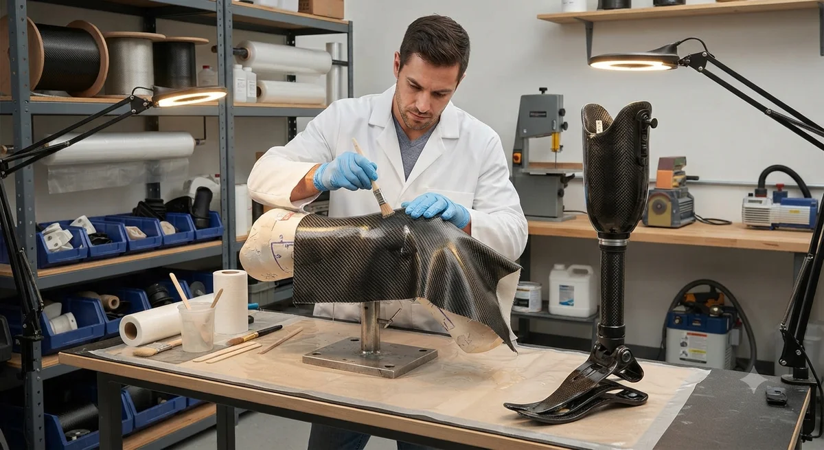
A detailed engineering analysis of carbon fiber composite propeller shafts for marine applications — covering torsional performance, critical speed calculations, vibration damping characteristics, bearing load reduction, and wet-environment durability. Includes design methodology for shaft sizing, metal-end fitting bonding strategies, and comparative test data against stainless steel (AISI 316) and aluminum-bronze shaft materials for planing hulls, luxury yachts, and high-speed patrol craft.
Introduction: The Marine Propeller Shaft Challenge
The propeller shaft is one of the most mechanically demanding components in a marine propulsion system. It must transmit engine torque (typically 500-10,000+ Nm in performance vessels) to the propeller while withstanding bending loads from the propeller's thrust and weight, torsional vibration from engine firing pulses, axial loads from propeller thrust (both ahead and astern), and lateral vibration from shaft rotation and propeller-induced excitation. It operates in a corrosive seawater environment, often with partial exposure to air at the shaft log and stern gland, creating a corrosion cell that challenges even stainless steel and nickel-aluminum-bronze alloys. The shaft must also operate below its critical speed (first lateral bending mode) across the entire engine RPM range — a requirement that becomes increasingly difficult as vessels become lighter and faster, because longer, thinner shafts have lower natural frequencies.
Carbon fiber reinforced polymer (CFRP) propeller shafts address these challenges through three fundamental material advantages: density approximately one-fifth that of stainless steel (1.55 g/cm³ vs 7.95 g/cm³ for AISI 316), specific stiffness (E/ρ) approximately three times higher than steel, and intrinsic vibration damping 10-30 times higher than metallic shafts. These properties translate to shafts that are 65-75% lighter than equivalent steel shafts, can be 30-50% longer before reaching critical speed limits, and transmit significantly less vibration to the hull structure through the bearings. The global market for composite marine shafts is projected to grow from $85 million in 2025 to $210 million by 2032, driven by demand in luxury yachting (where noise, vibration, and harshness are paramount), high-speed patrol craft (where weight reduction directly improves acceleration and top speed), and racing sailboats (where every kilogram of rotating mass affects performance).
Torsional Performance and Shaft Sizing
The primary design criterion for a CFRP propeller shaft is torsional strength — the ability to transmit the engine's maximum torque without failure. For a tubular CFRP shaft, the maximum torsional stress occurs at the outer surface and is given by τ_max = (T × r_o) / J, where T is the applied torque, r_o is the outer radius, and J is the polar moment of inertia. For a thin-walled tube, J = (π/2) × (r_o⁴ — r_i⁴). The torsional strength of a CFRP shaft depends on the fiber orientation: fibers at ±45° to the shaft axis provide the highest torsional strength, while 0° fibers (aligned with the shaft axis) contribute bending stiffness and axial strength but little torsional capacity. The standard CFRP shaft design uses a multi-axial laminate with 60-75% of plies at ±45° (torque transmission), 15-25% at 0° (bending stiffness and axial load), and 10-15% at ±90° (hoop strength for lateral pressure from bearings and shaft seals).
| Parameter | AISI 316 Stainless Steel | Aluminum-Bronze (CA104) | CFRP (60% ±45°, 20% 0°, 20% ±90°) | Unit |
|---|---|---|---|---|
| Density | 7.95 | 7.50 | 1.55 | g/cm³ |
| Tensile modulus (axial) | 193 | 120 | 55-75 (0° dominated) | GPa |
| Shear modulus (torsion) | 76 | 44 | 18-28 (±45° dominated) | GPa |
| Ultimate torsional strength | 250-350 (yield) | 200-280 (yield) | 180-320 | MPa |
| Damping ratio (structural) | 0.001-0.003 | 0.002-0.004 | 0.015-0.045 | — |
| Corrosion rate in seawater | 0.05-0.15 mm/year (pitting) | 0.02-0.08 mm/year | Zero (non-metallic) | — |
| Shaft weight (2.5m length, 80mm OD, 6mm wall) | 47.5 | 44.8 | 9.3 | kg |
| Critical speed (1st lateral mode, same geometry) | 3,100 | 3,200 | 7,800 | RPM |
| Typical shaft cost (OEM) | $800-$2,500 | $1,200-$3,500 | $2,500-$6,500 | USD |
The weight reduction provided by CFRP shafts has direct operational benefits. On a 40-knot patrol boat with twin 1,500 hp engines, replacing two 3.0-meter stainless steel propeller shafts (each 82 kg including flanges) with CFRP equivalents (each 24 kg) saves 116 kg of rotating mass. This reduced mass lowers the bearing loads at each shaft support (typically 3-5 bearings per shaft) by 55-65%, extends bearing service life by 2-4 times, and reduces the shaft alignment sensitivity during installation. The 116 kg weight saving also reduces the vessel's lightship weight, providing a secondary fuel efficiency benefit of approximately 0.5-1.0% reduction in fuel consumption at cruising speed, or alternatively, increased payload capacity.
Vibration Damping and Hull Quieting
The vibration damping advantage of CFRP shafts — with a structural damping ratio 10-30 times higher than metallic shafts — is perhaps the most valued property for luxury yacht and naval applications. In a conventional metallic shaft system, torsional vibration from engine firing pulses (typically at 10-50 Hz for a six-cylinder diesel at 600-3,000 RPM, with harmonics up to 300 Hz) propagates through the shaft, through the intermediate bearings and thrust bearing, and into the hull structure as structure-borne noise. This vibration is measurable as hull acceleration levels of 0.5-5.0 m/s² (RMS) in the vicinity of the shaft alley on a typical planing yacht. CFRP shafts reduce transmitted vibration by 8-15 dB across the 50-500 Hz frequency range — equivalent to a 60-85% reduction in vibration amplitude — due to the viscoelastic damping of the epoxy matrix and the internal friction at fiber-matrix interfaces.
- Torsional vibration attenuation: CFRP shafts reduce peak-to-peak torsional vibration amplitude by 50-70% compared to AISI 316 shafts of equivalent torque capacity, as measured at the propeller end. This reduces the load on the flexible coupling and extends coupling service life by 2-3×.
- Lateral vibration margins: The higher specific stiffness of CFRP increases the first lateral critical speed by 80-120% for the same shaft geometry, or allows a 30-50% longer shaft for the same critical speed — enabling single-piece shafts in applications that would otherwise require a two-piece shaft with a center bearing.
- Whirling mode separation: The wider separation between the first and second lateral whirling modes in CFRP shafts (typically 2.0-2.5× ratio for CFRP vs 1.3-1.6× for steel) reduces the risk of resonance excitation during engine start-up and shut-down transients.
- Underwater radiated noise: In naval applications (mine countermeasure vessels, submarines), the reduced vibration transmission from CFRP shafts translates to 5-12 dB reduction in underwater radiated noise at shaft-rate frequencies, improving acoustic stealth.
Metal End-Fitting Design and Bonding
The interface between the CFRP shaft tube and the metallic end fittings (shaft flange at the engine/gear coupling end, propeller flange or taper at the propeller end) is the most critical design feature of a composite propeller shaft. The bond must transmit full engine torque (up to 10,000+ Nm for large yachts) and axial thrust (up to 150 kN for a 1,500 hp vessel) without slip, creep, or fatigue failure over the shaft's service life (typically 5,000-20,000 operating hours). Three primary end-fitting designs are used in production CFRP marine shafts:
1. Adhesive-bonded splined insert: A metallic splined or grooved insert (typically 17-4PH stainless steel or Nitronic 50, precipitation-hardened to 35-40 HRC) is bonded into the CFRP tube using a two-part structural epoxy adhesive (such as 3M Scotch-Weld DP460 or Huntsman Araldite 2015). The insert has external splines or a diamond-pattern knurl (0.5-1.0 mm depth) to create a 10-15 mm thick adhesive bond line with mechanical interlock. The bond length is typically 1.5-2.5× the shaft outer diameter. This design achieves static torque capacities of 150-250 N·mm⁻² of bond area and fatigue endurance exceeding 10⁷ cycles at 50% of ultimate torque. Adhesive shear strength is verified through sub-element testing per ASTM D5868, with acceptance criteria of minimum 25 MPa apparent shear strength.
2. Bolted flange with metallic over-braid: The CFRP tube end is inserted into a metallic sleeve (typically 316L or 17-4PH stainless steel) that extends 100-200 mm along the shaft. Radial bolts (6-12 bolts per connection, M8-M16 grade 8.8 or higher) pass through both the sleeve and the CFRP tube. A carbon fiber over-braid (additional ±45° plies, 2-4 mm thick) is applied over the metallic sleeve region to distribute the bolt preload stresses and prevent local bearing failure of the composite. This design allows field replacement of the end fitting without replacing the entire shaft — a maintenance advantage valued by fleet operators. Bolt preload must be carefully controlled (typically 50-70% of bolt proof load) to avoid crushing the CFRP tube.
3. Compression-fit cone coupling: A metallic cone (taper 1:10 to 1:16) is pressed into or onto the CFRP tube end, creating a friction-based torque transmission joint. The cone is drawn into engagement using a central draw bolt, generating radial compressive stress at the CFRP-cone interface. This design has no adhesive — torque is transmitted entirely through friction — enabling complete disassembly for inspection and re-assembly without consumables. The coefficient of friction required for reliable torque transmission is 0.15-0.25 at the CFRP-metal interface, achievable with controlled surface roughness (Ra 3-8 μm on the metal cone surface).
| End-Fitting Design | Torque Capacity (Nm) | Max Axial Load (kN) | Installation Complexity | Maintenance | Relative Cost |
|---|---|---|---|---|---|
| Adhesive-bonded splined | 2,000-15,000 | 50-200 | Medium (curing time 24-72 h) | Non-serviceable | 1.0× (baseline) |
| Bolted flange + over-braid | 1,500-12,000 | 40-180 | High (torque control critical) | Field-replaceable | 1.2-1.5× |
| Compression-fit cone | 1,000-8,000 | 30-120 | Low (draw bolt only) | Fully serviceable | 0.9-1.3× |
Wet-End Durability and Seawater Protection
The portion of the propeller shaft that operates within the stern tube and extends into the seawater (the "wet end") presents the most challenging durability requirement for CFRP shafts. Prolonged seawater exposure can degrade the epoxy matrix through plasticization (water absorption, typically 0.8-1.5% by weight at saturation for epoxy, reducing the Tg by 5-15°C) and osmotic blistering if the laminate contains voids or incomplete cure. The standard protection strategy for CFRP marine shafts involves three barriers: (1) a gel coat or polyurethane topcoat (0.3-0.5 mm thick) applied to the outer surface of the shaft, providing UV protection and abrasion resistance against stern tube bearing wear; (2) a carbon fiber veil or glass fiber isolation layer (0.2-0.4 mm) at the outer laminate surface to prevent galvanic coupling if the shaft contacts a metallic stern tube; and (3) a vacuum-infiltrated resin-rich surface layer ensuring void content below 0.5% in the wet-end region. Accelerated aging tests (ASTM D1141 synthetic seawater at 60°C for 1,000 hours) show CFRP shafts with this three-barrier system retaining 92% of initial torsional strength and 88% of interlaminar shear strength — well within the safety margin for a shaft designed with a minimum 2.5:1 safety factor on ultimate strength.
Case Study: 28-Meter Luxury Motor Yacht
A 28-meter planing motor yacht powered by twin 1,600 hp MTU diesels was retrofitted from AISI 316 stainless steel propeller shafts (3.2 m length, 90 mm diameter, 8 mm wall thickness, weight per shaft: 68 kg) to CFRP shafts (3.2 m, 90 mm OD, 6 mm wall, weight per shaft: 21 kg). The CFRP shafts used the adhesive-bonded splined end-fitting design with ±45° dominant laminate. Key measured improvements over 18 months of operation (450 engine hours): bearing temperature reduction of 8-12°C at the stern tube (due to lower radial load from reduced shaft weight), vibration reduction of 11 dB at the shaft alley measurement point (50-200 Hz range), fuel consumption reduction of 1.8% at 28-knot cruising speed (attributed in part to reduced bearing friction from lower radial loads), and zero corrosion-related maintenance after 18 months versus the previous shafts requiring stern tube seal replacement at 12-month intervals due to shaft corrosion-related seal wear. The total cost premium for the CFRP shafts was approximately $6,800 per shaft (2.7× the stainless steel cost), with the owner projecting payback within 3 years based on fuel savings, extended maintenance intervals, and improved onboard comfort.
Frequently Asked Questions
How does the cost of a carbon fiber propeller shaft compare to stainless steel?
CFRP marine propeller shafts cost 2.5-4× the equivalent stainless steel shaft (OEM pricing: $2,500-$6,500 for CFRP vs $800-$2,500 for AISI 316). However, total cost of ownership over 5-10 years is often lower when accounting for: reduced fuel consumption (0.5-2.0%), extended bearing life (2-4×), elimination of corrosion-related maintenance, reduced vibration and noise, and longer shaft service life. Payback periods of 2-4 years are typical for vessels operating 500+ hours annually.
Can carbon fiber propeller shafts be repaired if damaged?
Yes, with limitations. Minor surface damage (gel coat cracks, superficial abrasion) can be repaired by sanding and re-coating. Deeper damage requiring structural repair is assessed per the composite repair manual: damage below 10% of wall thickness is typically cosmetic; 10-25% requires a bonded patch repair with scarf ratio 1:20 to 1:40; damage exceeding 25% wall thickness or involving the end-fitting bond joint typically requires shaft replacement. Most CFRP shaft manufacturers offer a repair and refurbishment service including re-bonding of end fittings.
What is the maximum power rating for a carbon fiber propeller shaft?
Production CFRP marine shafts are currently available for engines up to 2,500 hp (1,864 kW) per shaft, with shaft diameters up to 130 mm OD. Custom shafts for higher power ratings (up to 5,000 hp) have been demonstrated in naval and racing applications using larger diameters (up to 180 mm OD) and higher-modulus fibers (IM7, T800). Torque capacity is primarily limited by the end-fitting bond joint rather than the shaft tube itself, so design improvements in end-fitting technology directly extend the power envelope.
How do CFRP shafts perform in terms of fatigue life?
CFRP shafts exhibit excellent fatigue performance in torsional loading. S-N curve testing of ±45° dominant CFRP tubes at R = 0.1 (where R = minimum/maximum stress) shows no fatigue failure before 10⁷ cycles at 60% of ultimate torsional strength — a fatigue limit that exceeds AISI 316 (which has no defined fatigue limit but typically shows 50-60% endurance ratio at 10⁷ cycles). The key fatigue advantage of CFRP is in the marine environment: stainless steel's fatigue strength drops by 40-60% in seawater due to corrosion fatigue, while CFRP shows no seawater-related fatigue degradation. All CFRP marine shafts should be designed with a minimum fatigue safety factor of 2.0 based on the engine's maximum continuous torque.
What certifications apply to carbon fiber propeller shafts?
CFRP marine propeller shafts fall under classification society rules depending on vessel type and flag state. Key standards include: DNV-CG-0282 (Composite Propeller Shafts — design, manufacturing, and testing), Lloyd's Register Rules for the Classification of Composite Shafts (LR SS 10), ABS Guide for Composite Shafting (2024 edition), and ISO 12215-9 (Small Craft — Propeller Shaft Systems). For pleasure craft (CE category A, B, C), compliance with ISO 12215-9 and ISO 10088 is typical. For commercial and naval vessels, classification society type approval (DNV, LR, ABS, or BV) is required, involving prototype testing including static torsion to failure, torsional fatigue (10⁷ cycles), and seawater immersion accelerated aging (1,000 hours at 60°C).
Related Articles
- Carbon Fiber Mooring for Floating Offshore Wind: Fatigue and Corrosion in Deep Water
- Carbon Fiber Bicycle Frame Optimization: Layup Design and Manufacturing for Competitive Racing
- Carbon Fiber CFRP Retrofit for Infrastructure: Bridge and Building Seismic Strengthening
- Carbon Fiber Medical Imaging Equipment: Lightweight Gantry and Couch Structures for MRI/CT
- Carbon Fiber EV Battery Enclosures: Crash Safety and Electromagnetic Shielding Design
- Carbon Fiber Structures for Low-Altitude Economy: UAV Airframes and eVTOL Components
Interested in Our Products?
Contact our team for competitive pricing and technical specifications.
Get a QuoteRelated Products

Carbon Fiber Plate — 3K Twill T700 1.5mm
Thin 1.5mm carbon fiber plate with 3K twill weave surface. Lightweight and stiff, commonly used for covers, panels, drone bodies, and applications requiring a premium aesthetic appearance.

Carbon fiber standard plate-3k stripe
Lightweight, ultra-rigid standard sheets for drone fuselages, robot housings, facades and structural applications.

Square Carbon Fiber Tube — 3K Twill T700
Square cross-section carbon fiber tube manufactured with 3K twill weave for torsional strength. Preferred for structural frames, trusses, and support columns where rectangular geometry offers design flexibility.

Carbon Fiber Plate — 3K Twill T700 3.0mm
Medium-thickness 3.0mm carbon fiber plate offering significantly higher load capacity while maintaining attractive 3K twill finish. Suitable for structural brackets, reinforcement plates, and load-bearing panels.

Carbon Fiber Plate — UD Unidirectional T700
Unidirectional carbon fiber plate with all fibers oriented in a single direction for maximum strength along the fiber axis. Essential for structural reinforcements, splints, and applications where load direction is predictable.