
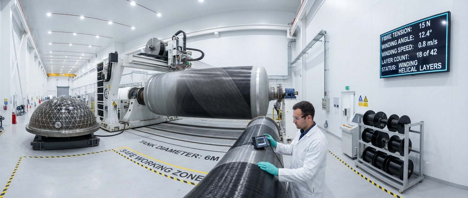
A comprehensive analysis of Type IV carbon fibre composite LNG fuel tanks for marine applications, covering liner materials, dome reinforcement design, cryogenic cyclic fatigue performance, IMO and class society certification requirements, and a comparative specification table of commercially available marine LNG tank systems.
Type IV Composite LNG Fuel Tanks: Enabling Maritime Decarbonisation
The International Maritime Organization (IMO) has set ambitious greenhouse gas reduction targets: a 40 % reduction in carbon intensity by 2030 (relative to 2008) and a 70 % reduction by 2050, with the ultimate goal of phasing out greenhouse gas emissions entirely within this century. Liquefied natural gas (LNG) has emerged as the most commercially viable transition fuel for deep-sea marine transport, offering 20–30 % CO₂ reduction compared to heavy fuel oil (HFO), near-zero SOₓ emissions, and 80–90 % reduction in NOₓ emissions when used with lean-burn gas engines. The adoption of LNG as a marine fuel has grown from 120 vessels in 2015 to over 1,200 LNG-capable vessels in service or on order as of mid-2026, driving corresponding demand for high-performance cryogenic fuel storage systems.
Type IV composite pressure vessels — consisting of a polymer liner (typically high-density polyethylene, HDPE, or polyamide 6, PA6) fully overwrapped with continuous carbon fibre filament wound reinforcement — represent the state of the art in marine LNG fuel tank technology. Compared to the earlier Type I (all-metal) and Type III (metal liner with composite wrap) designs, Type IV carbon fibre composite tanks offer 35–50 % weight reduction, complete corrosion resistance, and superior cryogenic fatigue performance, with a design life exceeding 30 years and 30,000 cryogenic pressure cycles. For a typical 500 m³ LNG fuel tank installation on a deep-sea container vessel, the weight saving of a Type IV system over a Type I steel tank is approximately 25–35 tonnes — weight that can be converted directly into increased cargo capacity or reduced fuel consumption.
YongXian CarbonFiber supplies two carbon fibre tow products specifically qualified for Type IV cryogenic filament winding: YongXian T700SC-50K (standard modulus 230 GPa, tensile strength 4,900 MPa, for the primary structural layers of the tank body) and YongXian T800HB-24K (intermediate modulus 295 GPa, tensile strength 5,880 MPa, for dome reinforcement and boss transition zones). Both products have received Classification Society Type Approval from Lloyd's Register (LR), Bureau Veritas (BV), and the China Classification Society (CCS) for marine cryogenic composite pressure vessel applications.
Design Architecture of Type IV Marine LNG Tanks
A Type IV marine LNG fuel tank consists of five distinct functional layers, each engineered for specific performance requirements at cryogenic temperatures (−162 °C for LNG at atmospheric pressure):
- Polymer liner (inner layer): HDPE or PA6 liner, 3–6 mm thickness, serving as the primary methane permeation barrier. The liner must maintain its ductility and impact resistance at −162 °C. PA6 liners are preferred for large marine tanks due to 40–50 % lower methane permeability than HDPE at cryogenic temperatures (0.8–1.2 g/m²/day vs. 1.5–2.5 g/m²/day for HDPE at 1 bar differential pressure). The liner is rotomoulded or injection-moulded in hemispherical dome sections that are welded together.
- Transition layer (cryogenic barrier): A thin glass fibre/epoxy layer (0.5–1.0 mm) wound directly onto the polymer liner. This layer provides thermal insulation between the carbon fibre structural layers and the cold liner, preventing the carbon fibre from reaching temperatures below −60 °C where microcracking of the epoxy matrix becomes a concern. The glass fibre layer also serves as a galvanic isolation barrier between the carbon fibre (cathodic) and any metallic fittings.
- Primary structural layer (hoop and helical wound carbon fibre): The main load-bearing structure, comprising 60–70 % of the total composite thickness. T700SC-50K carbon fibre tow is wound at helical angles of 10–15° (longitudinal reinforcement) and hoop angles of 87–90° (circumferential reinforcement). The helical-to-hoop thickness ratio is optimised to balance axial and hoop stresses generated by the internal pressure of the cryogenic liquid. For a 500 m³ tank operating at 0.7–1.0 MPa, the total structural wall thickness is 25–40 mm depending on the design safety factor.
- Dome reinforcement layer: The polar boss region — where the tank neck transitions from the cylindrical body to the hemispherical dome — experiences the highest localised stress in the structure. T800HB-24K intermediate modulus fibre is used here, with a locally increased thickness of 1.5–2.0× the body wall thickness. Geodesic dome winding patterns are used to follow the natural load paths.
- External protective layer (UV and abrasion barrier): A 1–2 mm gel coat or polyurethane coating applied to the outer surface. For marine applications, this layer must resist salt spray corrosion (ASTM B117, minimum 3,000 hours), UV degradation (ISO 4892, minimum 5,000 hours), and impact from mooring lines and fenders during port operations.
Comparative Specification: Type IV vs. Type I Marine LNG Tanks
| Parameter | Type IV — Carbon Fibre Composite | Type I — Steel (9 % Ni Steel / 5083 Al) | Type III — Aluminium Liner + Composite Wrap |
|---|---|---|---|
| Tank weight for 500 m³ LNG capacity (tonnes) | 18 – 25 | 55 – 70 | 32 – 42 |
| Weight saving vs. Type I (%) | 60 – 65 | — | 35 – 42 |
| Design pressure (MPa) | 0.7 – 1.0 | 0.7 – 1.0 | 0.7 – 1.0 |
| Operating temperature (°C) | −162 to +50 | −162 to +50 | −162 to +50 |
| Cryogenic fatigue life (cycles) | >30,000 | >10,000 | >15,000 |
| Boil-off rate (%/day, at 0.7 MPa) | 0.10 – 0.15 | 0.15 – 0.25 | 0.12 – 0.20 |
| Corrosion resistance | Excellent (no corrosion) | Moderate (requires coating) | Good (Al passive layer) |
| Methane permeation (g/m²/day) | 0.8 – 1.2 (PA6 liner) | Zero (metallic liner) | Zero (metallic liner) |
| Design life (years) | 30 – 35 | 20 – 25 | 20 – 30 |
| Initial cost index (per m³ capacity) | 1.8 – 2.2 | 1.0 | 1.4 – 1.6 |
| Life-cycle cost index (30 years, incl. maintenance) | 1.1 – 1.3 | 1.0 | 1.0 – 1.2 |
Cryogenic Cyclic Fatigue: The Defining Engineering Challenge
The most demanding engineering challenge for Type IV composite LNG fuel tanks is cryogenic cyclic fatigue. A marine LNG tank undergoes a full pressure cycle — from atmospheric pressure to maximum working pressure (0.7–1.0 MPa) and back — every time the vessel refuels and consumes LNG. With a typical refuelling interval of 12–20 days for deep-sea vessels, a tank designed for 30 years of service must withstand approximately 8,000–12,000 full cryogenic pressure cycles. The combination of cryogenic temperature (−162 °C) and cyclic pressure creates unique failure mechanisms not observed in ambient-temperature composite pressure vessels:
- Matrix microcracking at the fibre–matrix interface: The differential thermal contraction between the carbon fibre (CTE near-zero in the axial direction, approximately −1 × 10⁻⁶/°C in the transverse direction) and the epoxy matrix (CTE 40–60 × 10⁻⁶/°C) generates interfacial shear stresses of 20–40 MPa upon cooling from the cure temperature (120–150 °C) to the service temperature (−162 °C). After approximately 500–1,000 cryogenic thermal cycles, microcracks begin to appear in the epoxy matrix, propagating from the fibre–matrix interface into the interlaminar regions.
- Permeability degradation: As microcracks accumulate, the effective methane permeability of the composite wall increases. After 15,000 pressure cycles, permeability can increase by 2–3 orders of magnitude if the polymer liner is not functioning as a dedicated permeation barrier. This underscores the critical role of the HDPE or PA6 liner in Type IV tank design — the composite overwrap provides structural strength, but the liner must remain intact as the permeation barrier throughout the tank service life.
- Liner–composite interface fatigue: The bond between the polymer liner and the first glass fibre layer must withstand cyclic shear stresses generated by the differential expansion of the liner and composite during thermal cycling. Delamination at this interface is the most common failure mode in accelerated life testing of Type IV tanks.
Classification Society Certification Requirements
Marine LNG fuel tanks must be certified by an IMO-recognised classification society. The applicable rules for Type IV composite tanks are:
- International Code of Safety for Ships using Gases or other Low-flashpoint Fuels (IGF Code), adopted as SOLAS Chapter II-1 Part G. The IGF Code requires that LNG fuel tanks be designed for a minimum burst pressure of 4.0× the design pressure (4.0 MPa for a 1.0 MPa design pressure) and a fatigue life of at least 15,000 cryogenic pressure cycles.
- Lloyd's Register Rules for Composite Cryogenic Containment Systems (LR CCR 2025): Requires prototype testing including 15,000 cryogenic pressure cycles followed by a burst test, drop impact test (1 m drop onto a rigid surface at −162 °C), fire test (exposure to 650 °C hydrocarbon fire for 30 minutes with the tank at working pressure), and permeation test (methane leak rate < 0.5 g/m²/day at design pressure).
- Bureau Veritas NR 547 (Composite Cryogenic Vessels): Specifies a minimum design safety factor of 3.5 on ultimate strength for the composite overwrap, a minimum Tg of the epoxy resin of 120 °C (measured by DMA per ISO 6721), and 100 % NDE inspection — including phased-array ultrasonic testing (PAUT) of the boss transition zone and acoustic emission (AE) monitoring during hydrostatic proof testing.
- China Classification Society (CCS) Guidelines for Composite LNG Fuel Tanks (2024): Requires mandatory use of CCS Type-approved carbon fibre and epoxy resin systems, annual in-service inspection including vacuum infiltration testing of the composite wall, and replacement of the tank after 25 years or 20,000 cryogenic cycles, whichever comes first.
Frequently Asked Questions
How does the weight reduction of Type IV carbon fibre LNG tanks translate into operational savings for ship operators?
The 35–50 tonne weight saving of a Type IV tank compared to a Type I steel tank for a typical 500 m³ LNG installation has three direct economic benefits: (1) increased cargo capacity — the weight saving allows an additional 35–50 tonnes of payload, generating USD 1,500–3,000 in additional revenue per voyage depending on cargo type and freight rates; (2) reduced fuel consumption — every 10 tonnes of structural weight reduction on a deep-sea container vessel reduces main engine fuel consumption by approximately 0.15–0.20 % per voyage, saving USD 15,000–30,000 in annual fuel costs for the weight differential of a Type IV tank; and (3) improved trim and stability — the lower centre of gravity of a lighter tank system allows ship designers to optimise hull form for reduced resistance. On a 20-year operational horizon, the accumulative economic benefit of a Type IV tank system offsets its higher initial cost (1.8–2.2× the cost of a Type I tank) within 6–9 years of operation. For a 30-year vessel lifetime, the total cost of ownership of Type IV systems is 10–30 % lower than Type I systems, driven primarily by lower maintenance costs (no corrosion coating renewal) and higher cargo revenue.
What are the main technical barriers to widespread adoption of Type IV composite LNG tanks in the maritime sector?
The three main technical barriers are: (1) manufacturing scalability — the filament winding process for large marine tanks (500–5,000 m³ capacity) requires industrial-scale winding machines with 8–12 metre diameter capacity and multi-axis fibre placement heads, of which fewer than 20 exist globally; (2) certification cost — the prototype testing programme for a new Type IV marine LNG tank design (including cryogenic fatigue, burst, fire, drop impact, and permeation testing) costs USD 3–8 million and takes 12–24 months to complete; and (3) end-of-life recycling — carbon fibre composite tanks cannot be recycled through the same infrastructure as steel tanks, and the IMO's 2025 guidelines on composite waste management in ship recycling are still under development. However, these barriers are progressively being addressed: five new large-diameter filament winding machines are under construction in China, South Korea, and Europe (2025–2027); the classification societies have established standardised Type Approval procedures that reduce certification lead time; and YongXian CarbonFiber is participating in the IMO's Composite Ship Recycling Working Group to develop recycling guidelines for marine composite structures.
How does the methane slip from Type IV composite tanks compare to traditional steel LNG tanks?
Methane slip (unburned methane released to the atmosphere) is a critical environmental concern because methane has a global warming potential (GWP) 28–36 times that of CO₂ over a 100-year timeframe. Type IV composite tanks with polymer liners have inherently higher methane permeation than metallic-lined Type I or Type III tanks. A PA6-lined Type IV tank at 1.0 MPa operating pressure has a permeation rate of 0.8–1.2 g/m²/day, resulting in total methane loss of approximately 0.02–0.05 % of tank capacity per day from permeation alone. However, this permeation loss is captured by the tank ventilation system and directed to the vessel's gas combustion unit (GCU) or engine intake, where it is oxidised to CO₂, reducing the net methane slip to near-zero. The more significant methane slip concern for LNG-fuelled vessels is from engine combustion inefficiency (typically 1–3 % of fuel methane slip through the combustion process for lean-burn Otto-cycle gas engines), not from tank permeation. The IMO's Methane Abatement Programme targets a reduction in engine methane slip to below 0.5 % by 2030 through improved combustion chamber design and oxidising catalysts.
Market Outlook: Type IV Marine LNG Tanks 2026–2035
The market for Type IV composite LNG fuel tanks in marine applications is projected to grow from approximately USD 420 million in 2025 to USD 2.1 billion by 2035, representing a CAGR of 17.5 %. This growth is driven by three factors: the expanding LNG bunkering infrastructure (38 major LNG bunkering ports globally as of mid-2026, projected to exceed 80 by 2030), the IMO's tightening carbon intensity regulations (the Carbon Intensity Indicator, CII, becoming more stringent from 2027), and the increasing price competitiveness of carbon fibre composites as production scale increases. The Asia-Pacific region accounts for approximately 45 % of the global marine LNG tank market, driven by the large container ship fleets of China (COSCO), Japan (MOL, NYK, K Line), and South Korea (HMM). YongXian CarbonFiber's T700SC-50K and T800HB-24K carbon fibre tows are already specified in three Type IV marine LNG tank designs currently undergoing class certification in China and South Korea, positioning the company as a qualified supplier to the rapidly growing marine composite cryogenic tank market.
Part of topic
Related Articles
- Carbon Fiber Mooring for Floating Offshore Wind: Fatigue and Corrosion in Deep Water
- Carbon Fiber Bicycle Frame Optimization: Layup Design and Manufacturing for Competitive Racing
- Carbon Fiber CFRP Retrofit for Infrastructure: Bridge and Building Seismic Strengthening
- Carbon Fiber Medical Imaging Equipment: Lightweight Gantry and Couch Structures for MRI/CT
- Carbon Fiber EV Battery Enclosures: Crash Safety and Electromagnetic Shielding Design
- Carbon Fiber Structures for Low-Altitude Economy: UAV Airframes and eVTOL Components
Interested in Our Products?
Contact our team for competitive pricing and technical specifications.
Get a QuoteRelated Products

Carbon fiber standard plate-3k stripe
Lightweight, ultra-rigid standard sheets for drone fuselages, robot housings, facades and structural applications.

Square Carbon Fiber Tube — 3K Twill T700
Square cross-section carbon fiber tube manufactured with 3K twill weave for torsional strength. Preferred for structural frames, trusses, and support columns where rectangular geometry offers design flexibility.

Carbon Fiber Plate — 3K Twill T700 3.0mm
Medium-thickness 3.0mm carbon fiber plate offering significantly higher load capacity while maintaining attractive 3K twill finish. Suitable for structural brackets, reinforcement plates, and load-bearing panels.

Carbon Fiber Plate — 3K Twill T700 1.5mm
Thin 1.5mm carbon fiber plate with 3K twill weave surface. Lightweight and stiff, commonly used for covers, panels, drone bodies, and applications requiring a premium aesthetic appearance.

Carbon Fiber Plate — UD Unidirectional T700
Unidirectional carbon fiber plate with all fibers oriented in a single direction for maximum strength along the fiber axis. Essential for structural reinforcements, splints, and applications where load direction is predictable.