
On every orbital launch, the payload fairing is the first major component to fly and the last to be seen: it encloses the satellite during ascent, carries the aerodynamic and acoustic loads of the launch environment, and separates in two halves once the vehicle reaches space. For a mode
Introduction
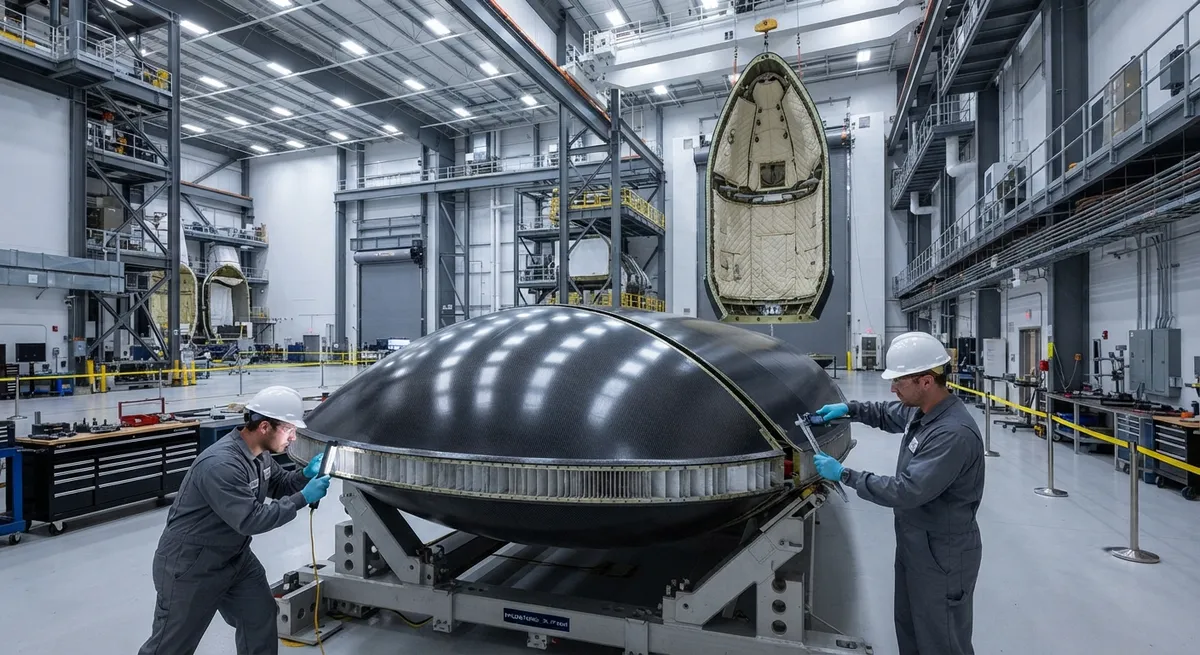
On every orbital launch, the payload fairing is the first major component to fly and the last to be seen: it encloses the satellite during ascent, carries the aerodynamic and acoustic loads of the launch environment, and separates in two halves once the vehicle reaches space. For a modern orbital rocket, the fairing is also the largest composite structure on the vehicle — typically 4-5 meters in diameter, 13-18 meters long for medium launch vehicles, and built almost entirely from carbon fiber skins over honeycomb core. Because the fairing is discarded at separation, its mass directly subtracts from payload capacity: every kilogram saved on the fairing is a kilogram added to the payload.
Designing a fairing is a balance of three disciplines. The structure must survive the acoustic and pressure environments of lift-off; the separation system must release it reliably and without collateral loads that could damage the satellite; and increasingly, the fairing must be recoverable and reusable if the vehicle's business model depends on it. This article walks through each of these design drivers with the quantitative detail relevant to carbon fiber suppliers and launch vehicle integrators.
The Fairing's Role and Load Environment
A payload fairing performs three functions during the roughly ten minutes from ignition to separation. It protects the satellite from aerodynamic heating and pressure during the dense atmosphere; it shields the payload from the acoustic and vibration environment generated by the engines and by aerodynamic flow; and it provides a clean aerodynamic shape that reduces drag and keeps the vehicle's trajectory efficient. The loads that dominate fairing design are surprising to many: they are not structural bending loads but acoustic loads. At lift-off, sound pressure levels inside the fairing can reach 140-150 dB, driven by the acoustic field radiated from the engine plume and reflected off the launch pad. These pressure fluctuations excite the large thin panels of the fairing, and the resulting vibration must be kept below levels the satellite can tolerate.
Acoustic Load Mitigation
Acoustic mitigation in fairings works at two levels: the blanket layer inside the fairing, and the stiffness and mass of the sandwich panels themselves. Sound transmission loss (STL) through a panel increases with both mass and stiffness, and the frequency range of concern — roughly 50-500 Hz for launch acoustics — is exactly where lightweight composite sandwich panels are weakest. Designers therefore add a dedicated acoustic blanket: a multi-layer quilt of fiberglass batting or melamine foam, typically 25-50 mm thick, covered with a thin impermeable film (often aluminized Mylar) that acts as a mass layer. The table below summarizes the contributions of each layer to the overall acoustic attenuation budget:
| Acoustic control element | Typical configuration | Attenuation at 100 Hz | Attenuation at 500 Hz | Added mass (kg/m²) |
|---|---|---|---|---|
| Bare CFRP sandwich panel | 0.5 mm skin / 25 mm honeycomb / 0.5 mm skin | 5-10 dB | 15-20 dB | — |
| Fiberglass batting blanket | 25-50 mm quilted batting | 5-8 dB | 8-12 dB | 1.0-1.5 |
| Impermeable film mass layer | Aluminized Mylar, 25-75 µm | 2-4 dB | 4-8 dB | 0.05-0.1 |
| Combined system | Panel + blanket + film | 12-20 dB | 25-35 dB | 1.2-1.7 |
This combination reduces internal sound pressure levels from 140-150 dB outside to roughly 120-128 dB at the payload interface — still high, which is why satellites are also designed and tested to acoustic levels, but manageable. The blanket is a deliberate mass penalty: 100-200 kg on a medium launch vehicle fairing, traded against the alternative of building the whole panel thicker, which would cost far more mass and stiffness-driven weight. Acoustic blankets remain the standard because they attenuate over a broad frequency band without adding structural stiffness where it is not needed.
Sandwich Construction for Large Thin-Wall Structures
The fairing structure itself is almost universally a sandwich: thin carbon fiber skins bonded to a honeycomb core, typically aluminum or aramid (Nomex) honeycomb. The skins carry the in-plane loads while the core separates them and carries the shear. This architecture gives the fairing the bending stiffness of a much thicker monolithic laminate at a fraction of the mass, which is essential for a 4-5 meter diameter shell that must resist handling, transport, and launch acoustic loads without excessive deflection or panel flutter. A comparison with stiffened skin construction makes the trade clear:
| Parameter | Sandwich (CFRP skins + honeycomb) | Stiffened skin (stringers/frames) |
|---|---|---|
| Typical areal weight, 4 m diameter | 4-6 kg/m² | 7-10 kg/m² |
| Bending stiffness at equal mass | 3-5x higher | Baseline |
| Surface smoothness | Excellent, no fastener heads | Good, fastener/splice details |
| Acoustic damping | Moderate (core adds some) | Lower |
| Manufacturing complexity | Core machining, film adhesive bonding | Frame assembly, riveting/bonding |
| Failure mode | Skin/core disbond, core crush | Skin buckling between stiffeners |
Sandwich construction wins for fairings because the load case is dominated by stiffness, acoustic response, and minimum mass over a large thin shell — exactly the regime where honeycomb sandwich excels. Carbon fiber skins are favored over fiberglass for the outer facesheet because the higher modulus reduces deflection and acoustic response, and because the thinner facesheet saves mass. On large fairings, skins are typically laid with automated fiber placement or roll-wrapped prepreg, then co-bonded to the core with film adhesive in autoclave or out-of-autoclave cure cycles.
Separation Systems
Fairing separation is a pyrotechnic and mechanical choreography that must be flawless: the two half-shells open and are pushed away without any contact with the payload, and the shock transmitted to the satellite must stay within limits. The standard architecture uses a longitudinal split line, a circumferential separation joint at the base, and an actuation system:
- Separation joint: a clamp band or frangible (explosive) cord along the longitudinal split and base circumference. Frangible joints cut cleanly but generate shock; clamp bands release with less shock but need preload management.
- Actuation: pneumatic pushers, spring thrusters, or hot-gas (pyrotechnic gas) thrusters mounted at the base push the two halves apart laterally after the joint releases.
- Separation sequence: once the vehicle's inertial sensors confirm the correct attitude, the joint fires, the pushers impart a relative lateral velocity of roughly 1-3 m/s, and the halves rotate about hinge points at the base or separate fully and tumble away.
Shock is the critical constraint: pyrotechnic separation can generate 1,000-3,000 g of transient shock at nearby equipment, so modern vehicles increasingly use low-shock non-pyrotechnic systems — shape-memory alloy release devices, redundant electromechanical latches, and pneumatic piston pushers. The fairing structure must be stiff enough to transmit the separation loads cleanly and to keep the two halves from re-contacting the payload as they separate, which drives local reinforcement at the split line and hinge fittings.
Reusability: The Recovered Fairing
The most significant change in fairing design in the past decade is reusability. A fairing is a substantial fraction of vehicle cost — typically 1-3 million USD for a medium launch vehicle — and recovering it transforms the launch economics. The leading reusable fairings deploy paraboloid-shaped guidance surfaces, cold-gas attitude thrusters, and steerable parafoils or parachutes to descend and be caught by ships or recovered from the ocean. Recovery imposes new design requirements on a component originally built to be discarded:
- Structural margin for recovery loads: the fairing must survive atmospheric re-entry heating, parachute deployment shock, and splashdown or net capture loads — new load cases on top of the ascent environment.
- Thermal protection: the leading surfaces experience moderate re-entry heating and need added thermal protection or sacrificial coatings.
- Water resistance: ocean-recovered fairings need corrosion protection for metal fittings, sealed avionics boxes, and drainage provisions, and rapid drying between flights.
- Inspection and requalification: recovered halves are inspected (ultrasonic testing of sandwich panels, fastener checks, and leak checks of sealed compartments) and requalified before reuse; the goal is 5-10 flights per fairing.
Because carbon fiber sandwich structures are stiff, light, and dimensionally stable, they tolerate the recovery cycle well — provided the design anticipated it. For the supply chain, reusable fairings are attractive programs: the material content per vehicle is comparable to expendable designs, but a single airframe flies repeatedly, so the long-term material demand is steadier and quality requirements are even higher.
Frequently Asked Questions
Why are payload fairings made of carbon fiber instead of aluminum?
Carbon fiber sandwich construction saves roughly 30-40% of fairing mass compared to an aluminum stiffened-skin design, and every kilogram saved translates directly into payload capacity on an orbital vehicle. The higher modulus of carbon skins also reduces deflection and acoustic response in the large thin panels, and the smooth, fastener-free surface simplifies the acoustic blanket interface and aerodynamic shaping. On a medium launch vehicle, the fairing mass reduction of 300-500 kg can be worth several hundred thousand dollars per launch in payload revenue.
How loud is the acoustic environment inside a fairing at launch?
Sound pressure levels inside the payload bay during lift-off typically reach 140-150 dB, generated by the engine plume acoustics reflecting off the launch pad. The acoustic blanket system — fiberglass or melamine foam batting covered with a thin impermeable film — combined with the stiffness of the sandwich panels reduces this to roughly 120-128 dB at the payload interface. That is still a severe environment, which is why satellites are designed and ground-tested to acoustic levels and why the blanket's 100-200 kg mass penalty is accepted as the most efficient attenuation strategy.
How does fairing recovery work, and how many times can a fairing be reused?
Reusable fairing halves use guidance surfaces and cold-gas thrusters to orient during descent, then deploy parafoils or parachutes to slow the fall. They are either caught by a ship with a net or recovered from the ocean. The fairing must be structurally designed for re-entry heating, parachute shock, and splashdown or capture loads from the start, since retrofitting recovery onto an expendable design is rarely practical. After each flight the halves are ultrasonically inspected, requalified, and returned to service; leading programs target 5-10 flights per fairing, which cuts the fairing cost contribution per launch by roughly an order of magnitude.
Conclusion
Carbon fiber payload fairings are the largest composite structures on orbital launch vehicles and among the most demanding in their load spectrum: acoustic environments above 140 dB, pyrotechnic separation shock, and — increasingly — the thermal and impact loads of atmospheric recovery. Sandwich construction with carbon skins and honeycomb core delivers the stiffness-to-mass ratio the large thin shells require, acoustic blankets handle the noise budget efficiently, and low-shock separation systems protect the payload while reusable fairings rewrite the vehicle cost model.
For launch vehicle integrators and composite suppliers, the practical factors are honeycomb core quality, film adhesive bonding reliability, and structural margin for recovery loads. Explore our carbon fiber fabric and prepreg range suited to large sandwich structures, or contact our engineering team to discuss fairing panel prototyping and material qualification for your launch vehicle program.
Related Articles
- Carbon Fiber Tube for Sale: Comparing Listings and Avoiding Bad Specs
- Carbon Fiber Engine Parts: High-Temperature Performance for Racing and Performance Vehicles
- Carbon Fiber Body Parts: Automotive Exterior Panels and Structural Components
- Carbon Fiber Drone Body Manufacturing: Monocoque Design and Production Methods
- Carbon Fiber Drone Parts Supplier: FPV Frames, Arms and Structural Components
- Filament Wound Epoxy Tubes: Industrial Applications from Oil and Gas to Aerospace
Interested in Our Products?
Contact our team for competitive pricing and technical specifications.
Get a QuoteRelated Products

Carbon fiber standard plate-3k stripe
Lightweight, ultra-rigid standard sheets for drone fuselages, robot housings, facades and structural applications.

Carbon Fiber Plate — 3K Twill T700 3.0mm
Medium-thickness 3.0mm carbon fiber plate offering significantly higher load capacity while maintaining attractive 3K twill finish. Suitable for structural brackets, reinforcement plates, and load-bearing panels.

Carbon Fiber Plate — 3K Twill T700 1.5mm
Thin 1.5mm carbon fiber plate with 3K twill weave surface. Lightweight and stiff, commonly used for covers, panels, drone bodies, and applications requiring a premium aesthetic appearance.

Square Carbon Fiber Tube — 3K Twill T700
Square cross-section carbon fiber tube manufactured with 3K twill weave for torsional strength. Preferred for structural frames, trusses, and support columns where rectangular geometry offers design flexibility.

Carbon Fiber Plate — UD Unidirectional T700
Unidirectional carbon fiber plate with all fibers oriented in a single direction for maximum strength along the fiber axis. Essential for structural reinforcements, splints, and applications where load direction is predictable.