
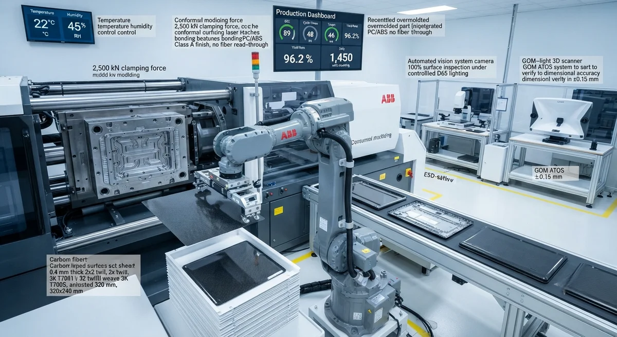
Technical guide to carbon fiber injection overmolding for consumer goods — combining stamped or continuous CFRP inserts with injection-molded thermoplastics for lightweight, ergonomic products with production cycle times under 60 seconds.
Introduction: The Convergence of Composites and Mass Production
Injection overmolding of carbon fiber composites — a hybrid manufacturing process where a pre-formed carbon fiber reinforced polymer (CFRP) insert is placed into an injection mold and overmolded with thermoplastic resin — has emerged as a breakthrough technology for producing consumer goods that combine the structural performance of carbon fiber with the design freedom, surface finish, and production speed of injection molding. Unlike traditional CFRP manufacturing (prepreg layup + autoclave, cycle times of 2–8 hours), overmolding achieves cycle times of 30–60 seconds per part, enabling production volumes of 100,000–1,000,000 units per year per mold. The global market for overmolded composite components in consumer goods was estimated at USD 1.2 billion in 2025, with applications spanning smartphone cases, laptop enclosures, sporting goods, power tool housings, automotive interior trim, and personal care products.
This article provides a detailed technical analysis of carbon fiber injection overmolding for B2B buyers and product development engineers. We cover material selection (CFRP insert types and overmolding thermoplastics), process parameters, tooling design, bond strength between insert and overmold, cost modeling for volume production, and quality control methods. Real production data from consumer electronics and sporting goods applications are included.
Material System Comparison: CFRP Inserts for Overmolding
| Insert Type | Reinforcement Form | Fiber Volume Fraction | Thickness Range | Tensile Modulus (GPa) | Insert Cost per cm² | Best For |
|---|---|---|---|---|---|---|
| Stamped CF SMC (Sheet Molding Compound) | Chopped fiber (25–50 mm), random orientation | 35–50% | 0.5–3.0 mm | 15–28 | $0.08–$0.15 | Complex 3D shapes, low-cost consumer goods |
| Unidirectional CF tape (UD tape) | Continuous fiber, single orientation | 50–65% | 0.15–0.50 mm per ply | 70–140 | $0.20–$0.50 | High stiffness ribs, structural inserts |
| CF woven fabric prepreg (2×2 twill, 3K) | Continuous fiber, bidirectional | 45–58% | 0.20–0.50 mm per ply | 50–70 | $0.25–$0.60 | Visible surfaces, laptop covers, phone cases |
| CF fiber-reinforced thermoplastic (CFRTP) stampable sheet | Continuous or chopped fiber in thermoplastic matrix (PA, PC, PPS) | 40–55% | 0.3–2.0 mm | 25–55 (chopped), 60–100 (continuous) | $0.15–$0.40 | High throughput, recyclable designs |
| CF non-woven veil (mat) | Chopped fiber (6–12 mm), random | 15–30% | 0.2–0.8 mm | 8–15 | $0.05–$0.12 | EMI shielding layers, low-cost reinforcement |
Overmolding Thermoplastic Selection
| Thermoplastic Resin | Melt Temperature (°C) | Mold Temperature (°C) | Flexural Modulus (GPa) | Typical Shrinkage (%) | Bond Strength to CF Insert (MPa) | Application Example |
|---|---|---|---|---|---|---|
| Polycarbonate (PC) | 280–320 | 80–120 | 2.3 | 0.5–0.7 | 8–14 | Smartphone cases, laptop housings |
| PC/ABS blend | 250–290 | 60–100 | 2.1 | 0.5–0.6 | 7–12 | Power tool housings, automotive trim |
| Polyamide 6 (PA6, nylon) | 240–280 | 80–120 | 2.8 (dry), 1.0 (conditioned) | 0.7–1.5 | 10–18 | Sporting goods, high-temp consumer products |
| Polyamide 66 (PA66) | 280–310 | 80–120 | 3.0 (dry), 1.2 (conditioned) | 1.0–2.0 | 12–20 | Automotive interior, power tool housings |
| Polypropylene (PP) | 200–260 | 30–80 | 1.5 | 1.0–2.5 | 3–6 | Low-cost consumer goods, packaging |
| Acrylonitrile Butadiene Styrene (ABS) | 220–260 | 50–80 | 2.0 | 0.4–0.9 | 5–9 | Consumer electronics housings |
| Polyetheretherketone (PEEK) | 370–400 | 160–200 | 3.9 | 0.5–1.0 | 15–25 | High-end sports equipment, medical devices |
Key Process Parameters for CF Injection Overmolding
- Insert preheating: The CFRP insert must be preheated to 80–160°C (depending on the overmolding resin) before being placed into the injection mold. Preheating serves two critical functions: (a) it prevents rapid cooling of the injected thermoplastic at the insert surface, ensuring adequate melt flow and bonding; (b) it reduces thermal stress between the insert (CTE = 2–7 ppm/°C for CFRP) and the overmold material (CTE = 50–100 ppm/°C for unfilled thermoplastics). Without preheating, the interfacial shear strength drops by 40–60% and warpage increases by 3–5×. Infrared preheating (3–5 seconds for a 0.5 mm insert) or conductive preheating in a heated mold cavity (8–15 seconds) are the two common methods.
- Insert surface preparation: Mechanical interlock between the CFRP insert and overmold is the primary bonding mechanism. The insert surface should have a controlled roughness (Ra = 2–8 µm) achieved by: (a) using a textured mold surface during CFRP insert consolidation (produces a woven fabric imprint with 20–50 µm peak-to-valley topography); (b) laser ablation or plasma treatment to create micro-pores (5–20 µm diameter, 10–50 µm depth) for resin penetration; (c) applying a thin thermoplastic tie layer (0.05–0.15 mm) co-cured onto the CFRP insert surface during insert manufacturing. Plasma treatment alone improves bond strength by 30–80% compared to untreated surfaces by increasing surface energy from 35–40 mJ/m² to 55–70 mJ/m².
- Injection parameters: Optimal injection parameters for CF overmolding differ significantly from standard injection molding: higher melt temperature (+10–25°C above the resin's standard range) to compensate for heat loss to the insert; slower injection speed (30–60% of standard) to prevent fiber wash-out from the insert surface and to allow the molten polymer to penetrate surface features without trapping air; and higher packing pressure (120–150% of standard) to compensate for differential shrinkage between the insert and overmold. Typical injection pressure is 800–1,500 bar for CF overmolding, versus 600–1,000 bar for standard injection molding of the same resin.
- Mold design considerations: The injection mold for CF overmolding requires: (a) insert positioning features — vacuum channels, mechanical locators, or magnetic holders to secure the CFRP insert (±0.05 mm positioning accuracy); (b) generous draft angles (3–5°) on the insert to facilitate demolding without damaging the carbon fiber surface; (c) hot runner systems with valve gates for precise control of melt flow around the insert; (d) conformal cooling channels (additively manufactured or CNC-machined) to achieve uniform mold temperature (±3°C across the cavity) and minimize part warpage.
- Cycle time optimization: A typical CF overmolding cycle: insert placement (3–8 seconds, robotic), mold close (1–2 seconds), injection (1–3 seconds), packing (3–8 seconds), cooling (15–40 seconds), mold open and part ejection (2–4 seconds), total: 25–65 seconds. The cooling phase is the rate-limiting step — determined by the overmold thickness and the insert's low thermal diffusivity (0.5–1.5 mm²/s for CFRP vs 90 mm²/s for aluminum). Thinner overmold sections (1.0–2.5 mm) combined with conformal cooling channels reduce cooling time by 30–50%.
- Warpage and dimensional control: The CTE mismatch between CFRP (2–7 ppm/°C) and overmold thermoplastics (50–100 ppm/°C) creates residual stress that causes part warpage. Mitigation strategies: (a) symmetric overmold thickness on both sides of the insert (balanced construction); (b) fiber orientation in the overmold (glass or carbon fiber-filled thermoplastics reduce overmold CTE by 40–60%); (c) annealing after molding (80–120°C for 30–60 minutes, depending on resin) to relieve residual stress; (d) mold temperature optimization — higher mold temperatures reduce differential cooling rates. With optimized parameters, parts with warpage below 0.3 mm over a 200 mm length are achievable.
Case Study: Carbon Fiber Overmolded Laptop Enclosure
A consumer electronics manufacturer developed a 14-inch laptop top cover (A-cover) using carbon fiber overmolding. The insert was a 0.4 mm 2×2 twill prepreg (3K T700S carbon fiber, epoxy matrix) with laser-etched surface features for bonding. The overmold was PC/ABS (Bayblend T85, Covestro) with 30% glass fiber content for CTE reduction. Key results after production ramp to 500,000 units/year:
- Weight: 68 g (CF insert) + 42 g (overmold) = 110 g total, vs 175 g for a conventional magnesium alloy A-cover — 37% weight reduction
- Stiffness: Flexural modulus 42 GPa (CF insert direction) vs 12 GPa for magnesium AZ91; part deflection at 5 N center load: 0.12 mm (CF) vs 0.35 mm (Mg) — 66% less deflection
- Surface quality: Class A surface finish (Ra 0.2 µm) with no visible fiber read-through or sink marks
- Drop test (MIL-STD-810H): 26 drops from 1.22 m onto plywood — no structural failure, only cosmetic scuffing at corners
- Cycle time: 48 seconds (target: 55 seconds) — 21% faster than initial target
- Yield rate: 96.2% after process optimization (up from 89% in pilot production)
- Tooling cost: $185,000 (single-cavity family mold with hot runner and conformal cooling)
- Unit cost at 500K/yr volume: $4.35 (CF insert $1.80, overmolding $2.55) vs $3.70 for magnesium alloy — 18% cost premium justified by weight and stiffness advantages and elimination of secondary painting (class-A surface from mold)
Quality Control and Testing for Overmolded CF Parts
| Test | Method | Acceptance Criteria | Frequency | Cost per Test |
|---|---|---|---|---|
| Insert-to-overmold bond strength | Pull-off test (ASTM D4541) or lap shear (ASTM D1002) | ≥8 MPa (pull-off), ≥12 MPa (lap shear) | 1 per 100 parts | $15–$30 |
| Visual surface inspection | Controlled lighting (D65), 300 lux minimum | No visible defects: sink marks, weld lines, burn marks, fiber read-through | 100% | $0.02/part (automated) |
| Dimensional inspection | CMM or white-light scanning (GOM ATOS) | ±0.15 mm on critical features, ±0.30 mm on overall dimensions | 1 per 50 parts | $5–$15 |
| Short-shot / fill analysis | Periodic short-shot molding (90% fill) | Complete coverage of insert; no unfilled regions | 1 per 500 parts or tool maintenance | $25–$50 |
| Thermal cycling | −20°C to +70°C, 4-hour cycles, 10 cycles total | No delamination, interfacial cracking, or warpage >0.5 mm | 1 per 1,000 parts (qualification) | $100–$200 |
| CTE verification | TMA (thermomechanical analysis) per ASTM E831 | CTE within ±15% of specification | 1 per material lot | $100–$250 |
Frequently Asked Questions
What is the minimum production volume that justifies CF overmolding tooling investment?
The break-even analysis depends on the part complexity and alternative manufacturing methods. For a typical consumer electronics enclosure (200 × 150 mm footprint), the tooling investment is $100,000–$250,000 for a single-cavity production mold with hot runner and conformal cooling. At a unit cost premium of $0.50–$1.50 over conventional injection molding (without CF insert), the minimum economic volume is 80,000–200,000 units per year to recover the incremental tooling cost within 2 years. However, if the CF overmolded part replaces a metal (magnesium or aluminum) part with secondary finishing (painting, anodizing, coating), the unit cost comparison shifts in favor of CF overmolding at volumes as low as 30,000–80,000 units/year, because the overmolded part achieves Class A surface finish directly from the mold, eliminating the $2–$5/part finishing cost. For sporting goods applications (golf club shafts, bicycle components), volumes of 5,000–20,000 units/year can be economical using simpler, lower-cost tooling ($30,000–$80,000).
Can CF overmolded parts be recycled?
Recycling of CF overmolded parts depends on the thermoplastic matrix. For thermoplastic overmolds (PC, PA, PP, ABS) combined with thermoplastic-matrix CFRP inserts (CFRTP), the entire assembly can be mechanically recycled — shredded and recompounded into short-fiber-reinforced molding compounds. The recycled material retains approximately 70–85% of the original tensile modulus and 60–75% of the tensile strength after one recycling cycle. For thermoset-matrix CFRP inserts (epoxy) combined with thermoplastic overmolds, recycling is more challenging: the thermoset insert cannot be remelted. The current best practice is to separate the overmold from the insert by cryogenic grinding (liquid nitrogen, −196°C), which embrittles the thermoplastic and allows mechanical separation of the thermoset CF insert fragments. The separated epoxy-CF material is typically used as filler in construction materials or new compression molding compounds. Approximately 40–60% of the carbon fiber can be recovered via pyrolysis (500–700°C in inert atmosphere), but fiber tensile strength degrades by 15–30% during the process.
What are the common defects in CF overmolding and how are they prevented?
Six common defects: (1) Insert displacement: the CFRP insert shifts during injection due to unbalanced melt flow. Prevention: optimize gate location (center-gate the mold), use vacuum-assisted insert positioning (200–300 mbar), and add mechanical locators. (2) Fiber wash-out: injected melt erodes carbon fibers from the insert surface. Prevention: slower injection speed (30–60 mm/s), higher-viscosity resin grade, and pre-consolidation of the insert with a thin resin-rich surface layer (0.05–0.10 mm). (3) Sink marks over the insert: differential shrinkage reveals the insert outline on the overmold surface. Prevention: increase overmold thickness above the insert to ≥1.5 mm; use glass or carbon fiber-filled overmold material to reduce shrinkage by 30–50%. (4) Weld lines at insert edges: the melt flow front splits around the insert and recombines, creating a weld line with 40–60% lower strength. Prevention: place weld lines in non-cosmetic areas; increase melt temperature by 10–15°C at the recombining flow front using sequential valve gates. (5) Delamination: the overmold separates from the insert at the interface. Prevention: increase insert preheat temperature to 120–160°C; apply plasma treatment to the insert surface; design mechanical undercuts or through-holes in the insert for overmold penetration. (6) Flash at insert edges: molten thermoplastic flows between the insert and mold surface. Prevention: increase clamping force by 10–20%; ensure insert edge thickness tolerance of ±0.05 mm.
How does the CF overmolding process affect the structural properties of the carbon fiber insert?
The injection molding process subjects the CFRP insert to high shear stress (500–1,500 s⁻¹ at the melt front), high pressure (800–1,500 bar), and thermal shock (the insert surface temperature rises from the preheat temperature to the melt temperature in 0.5–2 seconds). These conditions can cause: (a) microcracking in the epoxy matrix of thermoset inserts if the preheat temperature is too low — the thermal shock creates tensile stresses of 10–20 MPa at the surface, exceeding the transverse tensile strength of unidirectional CFRP (5–15 MPa). Solution: preheat to within 30°C of the overmold melt temperature. (b) Fiber buckling in thin inserts (0.2–0.5 mm) under high injection pressure — the compressive stress on the insert during filling can reach 5–15 MPa, which is below the longitudinal compressive strength of CFRP (500–1,000 MPa) but can cause micro-buckling of fibers at the surface if the insert is poorly supported. Solution: support the insert on the opposite side with a core-side mold feature. (c) Residual stress due to differential cooling — the overmold cools and shrinks onto the CFRP insert, creating compressive residual stress (5–25 MPa) at the interface. This compressive stress is generally beneficial for bond strength but can cause warpage if asymmetric. With proper process parameters, the CFRP insert retains >95% of its original stiffness and strength after overmolding.
What design rules apply for CF inserts in overmolded consumer products?
Key design rules: (1) Minimum insert thickness: 0.3 mm for stamped SMC or UD tape, 0.2 mm for woven prepreg. Thinner inserts are difficult to handle robotically and prone to buckling during injection. (2) Edge distance: maintain at least 5 mm between the insert edge and the part edge to prevent flash and ensure complete encapsulation. (3) Hole and cutout features: if the insert requires holes or cutouts, maintain a minimum web width of 3 mm between adjacent features, and a fillet radius of at least 1.5 mm at internal corners to prevent stress concentration and fiber fraying during handling. (4) Overmold wall thickness: minimum 1.0 mm over the insert for adequate encapsulation and sink mark prevention; maximum 4.0 mm to avoid excessive cycle time. (5) Draft angle: minimum 2° on vertical walls of the overmold, 3–5° on surfaces that contact the insert edge. (6) Rib design: insert thickness-to-rib height ratio should not exceed 1:8 to avoid rib sink marks on the opposite surface. (7) Gate location: gate into the overmold section directly, not onto the insert surface — direct impingement can wash fibers from the insert. A fan gate or tab gate at the edge of the overmold section is preferred.
Conclusion
Carbon fiber injection overmolding is a transformative manufacturing process that bridges the gap between high-performance composite materials and high-volume consumer product production. By combining a pre-formed CFRP insert (providing structural stiffness, light weight, and aesthetic carbon fiber appearance) with an injection-molded thermoplastic overmold (providing complex geometry, ergonomic features, durable surface finish, and rapid cycle times), manufacturers can achieve product attributes that are unattainable through either process alone. The key considerations for B2B buyers evaluating this technology include: insert material selection (stamped SMC for cost-sensitive, woven prepreg for visible carbon surfaces, UD tape for high-stiffness applications); overmold resin compatibility with the insert matrix; tooling investment ($100,000–$250,000 for typical consumer electronics); minimum economic volumes (30,000–200,000 units/year depending on the alternative); and quality control protocols for bond strength verification. As the technology matures and material costs decrease with adoption volume, CF overmolding is projected to grow from USD 1.2 billion in 2025 to USD 3.5–4.5 billion by 2032, driven primarily by consumer electronics, automotive interior trim, and premium sporting goods applications.
Part of topic
Related Articles
- Carbon Fiber Mooring for Floating Offshore Wind: Fatigue and Corrosion in Deep Water
- Carbon Fiber Bicycle Frame Optimization: Layup Design and Manufacturing for Competitive Racing
- Carbon Fiber CFRP Retrofit for Infrastructure: Bridge and Building Seismic Strengthening
- Carbon Fiber Medical Imaging Equipment: Lightweight Gantry and Couch Structures for MRI/CT
- Carbon Fiber EV Battery Enclosures: Crash Safety and Electromagnetic Shielding Design
- Carbon Fiber Structures for Low-Altitude Economy: UAV Airframes and eVTOL Components
Interested in Our Products?
Contact our team for competitive pricing and technical specifications.
Get a QuoteRelated Products

Carbon Fiber Plate — 3K Twill T700 1.5mm
Thin 1.5mm carbon fiber plate with 3K twill weave surface. Lightweight and stiff, commonly used for covers, panels, drone bodies, and applications requiring a premium aesthetic appearance.

Carbon fiber standard plate-3k stripe
Lightweight, ultra-rigid standard sheets for drone fuselages, robot housings, facades and structural applications.

Square Carbon Fiber Tube — 3K Twill T700
Square cross-section carbon fiber tube manufactured with 3K twill weave for torsional strength. Preferred for structural frames, trusses, and support columns where rectangular geometry offers design flexibility.

Carbon Fiber Plate — 3K Twill T700 3.0mm
Medium-thickness 3.0mm carbon fiber plate offering significantly higher load capacity while maintaining attractive 3K twill finish. Suitable for structural brackets, reinforcement plates, and load-bearing panels.

Carbon Fiber Plate — UD Unidirectional T700
Unidirectional carbon fiber plate with all fibers oriented in a single direction for maximum strength along the fiber axis. Essential for structural reinforcements, splints, and applications where load direction is predictable.