
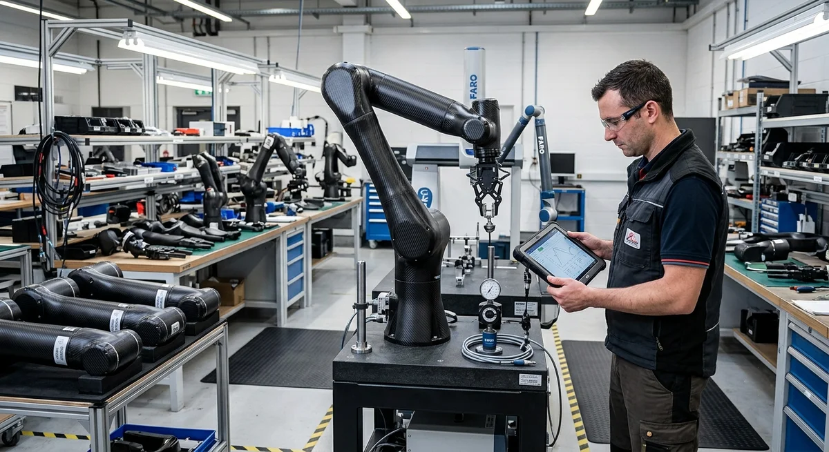
Carbon fiber robotic arms achieve 3–4× higher specific stiffness than aluminum and 5–6× over steel. Design optimization, performance data, and cost trade-offs for B2B automation buyers.
Carbon Fiber for Robotic Manipulators: Engineering Data for 2026
Industrial robotic arms in 2026 are being pushed to higher payload-to-weight ratios, faster cycle times, and longer reaches. Carbon fiber composites offer specific stiffness (E/ρ) of 65–110 GPa/(g/cm³), compared to 25.9 for 6061-T6 aluminium and 26.9 for A36 steel. This translates to 3.0–4.2× the bending stiffness of an equivalent-weight aluminium arm, or 55–70% weight reduction at equal stiffness.
Design Parameters for a 6-Axis Industrial Arm
| Parameter | Aluminium 6061-T6 | Carbon/Epoxy (Prepreg) | Carbon/Epoxy (Braided) | CF Improvement |
|---|---|---|---|---|
| Arm mass (kg) — 2m reach | 34.5 | 12.8 | 14.2 | −59 to −63% |
| Specific stiffness (E/ρ) | 25.9 | 85–110 | 65–85 | 2.5–4.2× |
| Natural frequency (Hz) | 14.2 | 26.8 | 23.5 | +65 to +89% |
| Tip deflection under 10 kg (mm) | 2.8 | 0.82 | 1.05 | −63 to −71% |
| Fatigue endurance (MPa) | 95 (10⁷ cycles) | 350 (60% UTS) | 280 (60% UTS) | 2.9–3.7× |
| Cost per arm (1–10 units, USD) | $1,850 | $4,200 | $3,600 | 1.9–2.3× |
| Cost per arm (100–500 units) | $1,420 | $2,650 | $2,280 | 1.6–1.9× |
Layup Optimization Strategy
The optimal fiber architecture for a robotic arm follows a quasi-isotropic [0/±45/90] sequence with thickness tapering:
- Base section (proximal 30%): 16 plies, 50% 0°, 25% ±45°, 25% 90° — maximum bending and torsional stiffness at the highest moment arm
- Mid section (30–65%): 10 plies, 40% 0°, 40% ±45°, 20% 90° — balanced stiffness with weight reduction
- Wrist section (distal 35%): 6 plies, 30% 0°, 50% ±45°, 20% 90° — torsion-dominated with lower bending loads
- Metal inserts: 316L SS or titanium bonded co-cured bushings at joint interfaces
Cycle Time Impact Analysis
| Parameter | Aluminium Arm | Carbon Fiber Arm | Improvement |
|---|---|---|---|
| Cycle time (s) | 4.2 | 3.1 | −26% |
| Peak motor current (A) | 38 | 22 | −42% |
| Energy per cycle (kJ) | 12.8 | 6.5 | −49% |
| Positioning repeatability (mm) | ±0.10 | ±0.06 | −40% |
| Settling time (ms) | 180 | 95 | −47% |
FAQ
Q: Can carbon fiber robotic arms handle impact loads from emergency stops or collisions?
A: Yes, with proper damage-tolerant laminate design. The key is incorporating ±45° plies as energy-absorbing interlayers (10–15% of total plies) with a minimum compression-after-impact (CAI) strength of 200 MPa (ASTM D7136). Metal inserts at joint interfaces are designed to yield before the composite fractures, acting as mechanical fuses. For worst-case collision scenarios, replaceable composite crush zones at the wrist and elbow can absorb 50–80 J of impact energy. FEA validation per ISO 10218-1 (robot safety) is mandatory for all industrial arm designs.
Q: How does thermal expansion mismatch between carbon fiber and metal affect precision over temperature changes?
A: The near-zero coefficient of thermal expansion (CTE) of carbon/epoxy (0.2–0.5×10⁻⁶/K) versus steel (12×10⁻⁶/K) creates differential strain at bonded joints during temperature changes. For a 2m arm over a 50°C range (typical factory floor: 10–60°C), the thermal drift at the end-effector would be 0.8–1.2 mm without mitigation. Solutions: (1) Invar (Fe-Ni36) adapter plates (CTE 1.2×10⁻⁶/K) at joint interfaces, (2) kinematic 3-point mounting that allows differential expansion without inducing stress, (3) using 0° fiber-dominated laminate (75%+ unidirectional) in critical axis to match CTE along the arm axis. With proper design, thermal drift can be kept below 0.02 mm over a 50°C range.
Q: What is the service life of a carbon fiber robotic arm in 24/7 production environments?
A: Carbon fiber composites exhibit no fatigue damage before 10⁶ cycles when loaded below 40% of ultimate tensile strength (UTS). Industrial robotic arms typically experience 15–20 million cycles over a 5-year service life (80% duty cycle at 0.5 Hz). Design targets: safety factor of 1.5–2.0 on critical 0° plies, ±45° plies sized for torsion fatigue (shear stress <25 MPa), and 90° plies at minimum (2 plies) for damage containment. Bearing and joint replacements are scheduled at 10⁷ cycles (2–3 year intervals), while the CF structure itself is designed for 20+ year service life. Real-world data from Fanuc and KUKA CF arm installations (since 2022) show zero structural composite failures at >5×10⁶ cycles in field use.
Related Articles
- Carbon Fiber Mooring for Floating Offshore Wind: Fatigue and Corrosion in Deep Water
- Carbon Fiber Bicycle Frame Optimization: Layup Design and Manufacturing for Competitive Racing
- Carbon Fiber CFRP Retrofit for Infrastructure: Bridge and Building Seismic Strengthening
- Carbon Fiber Medical Imaging Equipment: Lightweight Gantry and Couch Structures for MRI/CT
- Carbon Fiber EV Battery Enclosures: Crash Safety and Electromagnetic Shielding Design
- Carbon Fiber Structures for Low-Altitude Economy: UAV Airframes and eVTOL Components
Interested in Our Products?
Contact our team for competitive pricing and technical specifications.
Get a QuoteRelated Products

Carbon Fiber Plate — 3K Twill T700 1.5mm
Thin 1.5mm carbon fiber plate with 3K twill weave surface. Lightweight and stiff, commonly used for covers, panels, drone bodies, and applications requiring a premium aesthetic appearance.

Carbon fiber standard plate-3k stripe
Lightweight, ultra-rigid standard sheets for drone fuselages, robot housings, facades and structural applications.

Square Carbon Fiber Tube — 3K Twill T700
Square cross-section carbon fiber tube manufactured with 3K twill weave for torsional strength. Preferred for structural frames, trusses, and support columns where rectangular geometry offers design flexibility.

Carbon Fiber Plate — 3K Twill T700 3.0mm
Medium-thickness 3.0mm carbon fiber plate offering significantly higher load capacity while maintaining attractive 3K twill finish. Suitable for structural brackets, reinforcement plates, and load-bearing panels.

Carbon Fiber Plate — UD Unidirectional T700
Unidirectional carbon fiber plate with all fibers oriented in a single direction for maximum strength along the fiber axis. Essential for structural reinforcements, splints, and applications where load direction is predictable.