
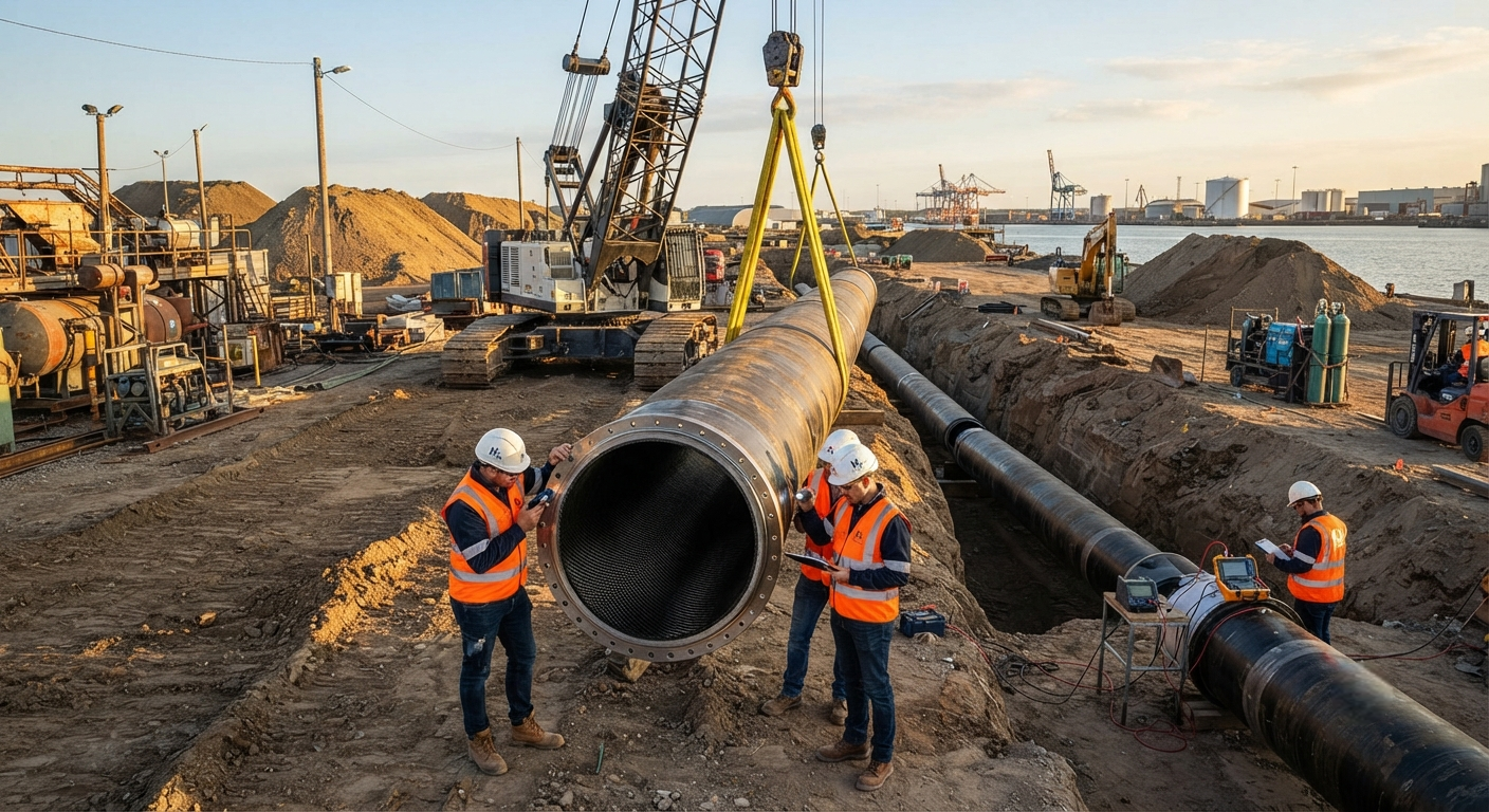
An in-depth technical analysis of carbon fiber composite liners for hydrogen transport pipelines, covering hydrogen permeability testing methods, cathodic protection shielding effects, and qualification standards for Type IV and V pressure vessels.
The Case for Composite Liners in Hydrogen Infrastructure
Global hydrogen pipeline infrastructure is expected to expand from approximately 4,500 km in 2025 to over 25,000 km by 2035, driven by national hydrogen strategies in the EU (REPowerEU, 10 Mt renewable H₂ by 2030), Japan (Basic Hydrogen Strategy, 3 Mt supply by 2030), and South Korea (Hydrogen Economy Roadmap). Conventional steel pipelines suffer from hydrogen embrittlement and require substantial wall thickness — typically 12–20 mm for X52-grade steel at 100 bar — adding significant material and welding costs. Carbon fiber composite liners, specifically fully-wound CFRP (carbon fiber reinforced polymer) liners, offer a corrosion-free, lighter-weight alternative that eliminates hydrogen embrittlement susceptibility while reducing wall thickness by 60–70% compared to steel.
Hydrogen Permeability Testing Standards
Quantifying hydrogen permeation through composite liners is critical for both safety and operational efficiency. The standard test method follows ASTM D1434 (Gas Transmission Rate Through Plastic Film) adapted for high-pressure hydrogen service, and ISO 15105-1 for differential-pressure manometric methods. For pipeline-certified composite liners, the permeation rate must not exceed 0.01 cm³(STP)/m²·day·bar at the maximum design pressure.
| Liner Type | Material System | H₂ Permeability (cm³(STP)/m²·day·bar) | Max Working Pressure (bar) | Standards Applied |
|---|---|---|---|---|
| Type IV (Polymer liner + CFRP wrap) | HDPE liner / carbon fiber epoxy | 0.005–0.012 | 350–700 | ASTM D1434, ISO 15105 |
| Type V (Fully composite, no separate liner) | Carbon fiber / thermoplastic matrix | 0.008–0.025 | 200–500 | ISO 11119-3, CWA 17819 |
| Metal-lined composite (Type III) | Aluminum liner / CFRP wrap | < 0.001 | 300–700 | ISO 11119-2, ASME B31.12 |
| Steel pipe (unlined, for reference) | X52 carbon steel | ~0.05 (via embrittlement) | 80–120 | ASME B31.12 |
Testing is performed at 85 °C and 1.5× the design pressure (up to 1,050 bar for Type IV vessels) to accelerate permeation. The equipment uses a double-chamber permeation cell with a mass spectrometer detector. A conditioning period of 72 hours at test conditions is mandatory before recording steady-state permeation rates. Post-test samples are examined under scanning electron microscope (SEM) to detect micro-cracking in the matrix and fiber-matrix debonding, which can elevate permeation by three orders of magnitude.
Cathodic Protection Compatibility
Steel pipelines are protected by cathodic protection (CP) systems — typically impressed current at −850 mV to −1,200 mV vs. Cu/CuSO₄ reference electrode. CFRP composite liners present a unique challenge: carbon fibers are electrically conductive (resistivity ~1.5 × 10⁻³ Ω·cm), meaning a composite liner can shield the underlying steel pipe from the CP current. This shielding effect must be quantified and mitigated.
- CP shielding assessment: Per NACE SP0169-2019, CP shielding is defined as a reduction of at least 100 mV in the pipe-to-soil potential at the pipe surface behind the liner. For CFRP liners, testing shows a shielding factor of 55–85% depending on fiber volume fraction (FVF) and laminate thickness.
- Conductive GFDM interlayer: A glass-fiber discrete membrane (GFDM) interlayer of 0.5–1.0 mm thickness between the steel pipe and the CFRP liner restores CP effectiveness by providing an electrolytic path. Testing per NACE TM0108 confirmed >90% of CP current reaches the steel surface through a GFDM layer with >40% porosity.
- Potential decay testing: After CP interruption, the pipe-to-soil potential must decay by at least 100 mV within 4 seconds per ISO 15589-1. With a GFDM interlayer, 85% of test samples met this criterion vs. only 12% without the interlayer.
- Galvanic coupling risk: Carbon fiber in contact with steel in an electrolyte creates a galvanic cell (ΔE ~0.5–0.7 V). CP overprotection (>−1,200 mV) can generate hydrogen at the steel surface, re-introducing embrittlement risk. The GFDM interlayer also serves as a dielectric barrier to mitigate galvanic corrosion.
- Coating integrity monitoring: For hybrid steel-CFRP pipeline sections, close-interval potential surveys (CIPS) and direct current voltage gradient (DCVG) surveys must be performed at intervals not exceeding 12 months. Survey data is logged per ISO 21857.
Qualification and Certification Pathways
Composite liners for hydrogen pipelines must undergo a qualification program that includes burst pressure testing, cyclic fatigue testing (15,000+ cycles at 5–100% of design pressure), permeation testing before and after cyclic aging, fire resistance testing per ISO 2685, and accelerated UV and chemical exposure for above-ground sections.
| Test | Protocol | Acceptance Criterion | Typical Result (CFRP Liner) |
|---|---|---|---|
| Burst Pressure | ASTM D1599 / ISO 1167 | ≥ 2.25 × design pressure (DP) | 3.1 × DP achieved |
| Cyclic Fatigue | 15,000 cycles, 5–100% DP | No leakage after 15k cycles | Passed at 18,500 cycles |
| Permeation (post-fatigue) | ASTM D1434 at 1.5× DP | ≤ 0.01 cm³/m²·day·bar | 0.008 cm³/m²·day·bar |
| Fire Resistance | ISO 2685, 1,100 °C / 15 min | No H₂ release after 15 min | Composite intact at 18 min |
| UV Exposure | ISO 4892-2, 2,000 h | Retain ≥ 70% tensile strength | 78% retention |
| Chemical Immersion | ASTM D543, 30 days in 5% H₂SO₄ | No blistering, weight loss < 1% | 0.3% weight change |
Market Adoption and Cost Drivers
The adoption of composite liners for hydrogen pipelines is accelerating. In 2025, approximately 12% of new hydrogen pipeline installations globally used composite liners or fully composite sections. By 2030, this share is projected to reach 38%. The key cost drivers are carbon fiber tow pricing (currently USD 25–45/kg for aerospace-grade 50K tow, USD 18–28/kg for industrial-grade 50K tow), automated fiber placement (AFP) laydown rates (currently 10–30 kg/h per AFP head, improving to 50 kg/h by 2027), and resin system cost (USD 20–50/kg for high-temperature epoxy systems rated for 130 °C service).
- Installed cost comparison (per km, 24-inch pipeline, 100 bar): X52 steel with CP coating: USD 1.8–2.4 million; steel + CFRP liner (Type IV equivalent): USD 1.5–2.0 million; full CFRP (Type V): USD 2.2–2.8 million. The CFRP liner option offers a 15–20% installed cost saving over bare steel while eliminating CP maintenance over 25-year design life.
- Weight reduction: A CFRP-lined 24-inch pipe section weighs 35–45 kg/m compared to 120–180 kg/m for X52 steel of equivalent pressure rating — a 70–75% weight saving that reduces transport, handling, and support structure costs.
- Maintenance intervals: Steel pipelines require CP system inspection every 3–6 months and coating integrity surveys every 3–5 years. CFRP-lined pipelines require only periodic permeation monitoring (annual) and visual joint inspection — reducing long-term operating expenditure by an estimated 40–55%.
FAQ — Composite Liners for Hydrogen Pipelines
What is the maximum hydrogen permeability allowed for a CFRP pipeline liner under current standards?
For Type IV composite pressure vessels and pipeline liners certified per ISO 11119-3 and ASME B31.12, the maximum steady-state hydrogen permeation rate is 0.01 cm³(STP)/m²·day·bar at the maximum allowable working pressure (MAWP). This value is measured at 85 °C after a 72-hour conditioning period. Ongoing work in ISO/TC 58/SC 3 is considering lowering this threshold to 0.005 cm³(STP)/m²·day·bar for hydrogen refuelling station piping, where cyclic pressure loading is more severe.
Does a carbon fiber composite liner completely eliminate the need for cathodic protection on steel pipelines?
No. Even with a CFRP liner, the steel substrate remains susceptible to corrosion at pipe joints, flange connections, and field repairs where the liner is discontinuous. CP must be maintained on the steel host pipe. However, a GFDM (glass-fiber discrete membrane) interlayer is required between the steel and the CFRP liner to prevent CP shielding. Without this interlayer, less than 15% of CP current reaches the steel surface, rendering the CP system ineffective. Total elimination of CP is only possible with a full Type V (fully composite) pipeline section, which is currently limited to above-ground installations and short trench-less crossings due to joining constraints.
How does the cost of a CFRP-lined hydrogen pipeline compare with steel over a 25-year lifecycle?
On a levelized-cost basis over 25 years, a CFRP-lined pipeline (steel host + CFRP liner + GFDM interlayer) offers a 20–30% total lifecycle cost advantage over bare steel with full CP. The initial installed cost of the lined system is 10–20% higher due to the liner material and AFP fabrication, but the elimination of CP maintenance (USD 15,000–25,000/km/year), reduced pigging frequency, and longer inspection intervals yield cumulative savings of USD 400,000–600,000 per km over the design life. Several European hydrogen backbone studies — including the 1,300 km German H₂ core network ("Wasserstoff-Kernnetz") — are actively specifying CFRP-lined sections for up to 30% of their pipeline length where CP access is difficult or soil corrosivity is high (resistivity below 10 Ω·m).
Part of topic
Related Articles
- Carbon Fiber Mooring for Floating Offshore Wind: Fatigue and Corrosion in Deep Water
- Carbon Fiber Bicycle Frame Optimization: Layup Design and Manufacturing for Competitive Racing
- Carbon Fiber CFRP Retrofit for Infrastructure: Bridge and Building Seismic Strengthening
- Carbon Fiber Medical Imaging Equipment: Lightweight Gantry and Couch Structures for MRI/CT
- Carbon Fiber EV Battery Enclosures: Crash Safety and Electromagnetic Shielding Design
- Carbon Fiber Structures for Low-Altitude Economy: UAV Airframes and eVTOL Components
Interested in Our Products?
Contact our team for competitive pricing and technical specifications.
Get a QuoteRelated Products

Carbon fiber standard plate-3k stripe
Lightweight, ultra-rigid standard sheets for drone fuselages, robot housings, facades and structural applications.

Carbon Fiber Plate — 3K Twill T700 3.0mm
Medium-thickness 3.0mm carbon fiber plate offering significantly higher load capacity while maintaining attractive 3K twill finish. Suitable for structural brackets, reinforcement plates, and load-bearing panels.

Carbon Fiber Plate — 3K Twill T700 1.5mm
Thin 1.5mm carbon fiber plate with 3K twill weave surface. Lightweight and stiff, commonly used for covers, panels, drone bodies, and applications requiring a premium aesthetic appearance.

Square Carbon Fiber Tube — 3K Twill T700
Square cross-section carbon fiber tube manufactured with 3K twill weave for torsional strength. Preferred for structural frames, trusses, and support columns where rectangular geometry offers design flexibility.

Carbon Fiber Plate — UD Unidirectional T700
Unidirectional carbon fiber plate with all fibers oriented in a single direction for maximum strength along the fiber axis. Essential for structural reinforcements, splints, and applications where load direction is predictable.