
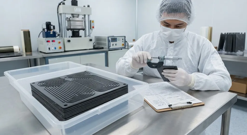
Proton exchange membrane (PEM) fuel cells convert hydrogen and oxygen into electricity and water, with bipolar plates comprising 60–80% of stack weight and cost. Each plate must simultaneously serve four functions: distribute hydrogen and air flow through micro-channels, conduct electro
Introduction
Proton exchange membrane (PEM) fuel cells convert hydrogen and oxygen into electricity and water, with bipolar plates comprising 60–80% of stack weight and cost. Each plate must simultaneously serve four functions: distribute hydrogen and air flow through micro-channels, conduct electrons between cells, remove product water, and provide structural support for the membrane electrode assembly (MEA). Traditional bipolar plates are machined from graphite or stamped from stainless steel or titanium, but both approaches face limitations — graphite is brittle and expensive to machine, while metals corrode in the acidic fuel cell environment, increasing interfacial contact resistance (ICR) over time.
Carbon fiber reinforced polymer (CFRP) composites with conductive fillers offer a promising alternative: lightweight construction with tunable conductivity, injection-moldable geometry, and inherent corrosion immunity. The challenge is achieving sufficiently low through-plane electrical resistance while maintaining mechanical integrity and gas impermeability. This article explains how CFRP bipolar plates are formulated, manufactured, and validated for fuel cell applications, providing practical guidance for material suppliers and stack manufacturers.
Bipolar Plate Functional Requirements
A bipolar plate in a PEM fuel cell stack must meet simultaneous demands across multiple performance domains:
- Electrical conductivity: Through-plane resistivity below 20 mΩ·cm² is required to minimize ohmic losses. Target values for automotive applications are 10–15 mΩ·cm² at a clamping pressure of 1–2 MPa.
- Gas impermeability: The plate must prevent hydrogen crossover between adjacent cells. Helium leak rates below 10⁻⁶ mbar·L/s are typically specified.
- Corrosion resistance: The fuel cell environment is acidic (pH 2–3), humidified, and电化学活跃. Plates must withstand potentials of 0.6–1.2 V vs. SHE with current densities below 1 μA/cm².
- Channel geometry: Flow field channels (0.3–1.0 mm deep, 0.5–2.0 mm wide) must be precisely formed to ensure uniform gas distribution and water removal.
- Mechanical strength: The plate must withstand clamping loads of 1–2 MPa without cracking, and survive vehicle vibration and thermal cycling.
These requirements create competing demands: higher filler loading improves conductivity but increases brittleness and reduces processability. The CFRP formulation must balance these trade-offs for each specific application.
CFRP Formulation for Conductive Bipolar Plates
Conductive CFRP bipolar plates combine carbon fiber reinforcement with conductive fillers in a thermoset or thermoplastic matrix. The formulation strategy targets three performance parameters:
| Component | Typical Loading | Function | Trade-off |
|---|---|---|---|
| Carbon fiber (chopped) | 30–50% by weight | Structural reinforcement, in-plane conductivity | Higher loading increases stiffness but reduces flow channel definition |
| Graphite flakes | 10–25% by weight | Through-plane conductivity, gas barrier | Improves conductivity but increases density and reduces strength |
| Carbon nanotubes / graphene | 1–5% by weight | Percolation network, inter-particle connectivity | Small additions dramatically improve conductivity; cost remains high |
| Resin matrix | 25–40% by weight | Binder, gas impermeability, corrosion resistance | Epoxy provides best chemical resistance; thermoplastics enable faster cycling |
The key to achieving low through-plane resistivity is creating a percolation network of conductive fillers that bridges the through-thickness direction. Chopped carbon fibers provide in-plane conductivity but limited through-thickness connectivity; graphite flakes and carbon nanotubes fill the gaps between fibers, creating continuous conductive pathways. A typical formulation achieves through-plane resistivity of 8–15 mΩ·cm² at 1.5 MPa clamping pressure, meeting automotive specifications.
Manufacturing Processes
Three manufacturing routes are used for CFRP bipolar plates, each with distinct advantages:
- Compression molding: A pre-measured charge of conductive CFRP compound is placed in a heated matched-die mold and compressed at 5–15 MPa for 30–120 seconds. This is the highest-volume process, capable of cycle times of 30–60 seconds per plate, and produces the best surface finish for channel geometry definition.
- Injection molding: A conductive thermoplastic compound (e.g., PPS + 40% carbon fiber + 15% graphite) is injection-molded into near-net shape plates. This enables complex 3D geometries and integrates features like gasket grooves, but achieves lower fiber volume fractions and higher contact resistance than compression molding.
- Transfer molding: A conductive thermoset compound is transferred into a closed mold under pressure. This process fills fine channel features well and provides good fiber wet-out, but cycle times are longer than compression molding (2–5 minutes per plate).
Post-molding operations typically include surface planarization (grinding or polishing to achieve flatness within ±10 μm), application of conductive coating or surface treatment to reduce ICR, and quality inspection for channel dimension accuracy and surface defects.
Performance Validation for Fuel Cell Stacks
Validating CFRP bipolar plates requires testing at the component level and within operating fuel cell stacks:
- Interfacial contact resistance (ICR): Measured as a function of clamping pressure using a four-point probe method. ICR must remain below 20 mΩ·cm² at 1.5 MPa throughout the plate's service life.
- Corrosion testing: Accelerated corrosion testing in simulated fuel cell conditions (0.1 M H₂SO₄, 80°C, 0.6–1.2 V vs. SHE) for 1,000–5,000 hours confirms stability of both ICR and mechanical properties.
- Gas permeability: Helium leak testing confirms gas crossover rates below specification limits, typically 10⁻⁶ mbar·L/s.
- Stack performance testing: Plates are assembled into short stacks (10–50 cells) and tested for polarization curve, power density, and durability over 1,000–5,000 hours of operation.
- Mechanical testing: Flexural strength, impact resistance, and vibration fatigue testing confirm the plate survives manufacturing, assembly, and vehicle operation.
Standards such as ISO 15118 for fuel cell vehicle interfaces, SAE J2617 for bipolar plate testing, and DOE technical targets for cost and performance provide the validation framework.
Frequently Asked Questions
How do CFRP bipolar plates compare to graphite and stainless steel?
CFRP plates offer 30–50% weight reduction compared to graphite at similar conductivity levels, with manufacturing costs 40–60% lower than machined graphite. Against stainless steel, CFRP provides corrosion immunity without the need for protective coatings, and lower density (1.6–1.8 g/cm³ vs. 7.9 g/cm³). The primary disadvantage is that CFRP through-plane conductivity (8–15 mΩ·cm²) is higher than stainless steel (2–5 mΩ·cm²) and approaching graphite (5–10 mΩ·cm²), requiring careful filler optimization. For automotive applications where weight and cost are primary drivers, CFRP plates are increasingly preferred over both alternatives.
What is the lifetime of CFRP bipolar plates in a fuel cell vehicle?
CFRP bipolar plates are designed for the full vehicle lifetime — typically 5,000–8,000 hours for passenger cars and 25,000–30,000 hours for heavy-duty trucks. The conductive filler network is inherently stable in the fuel cell environment, unlike metallic plates where corrosion products accumulate over time. Accelerated testing of 5,000 hours at 80°C and 0.8 V shows ICR increases of less than 10% for well-formulated CFRP plates, well within acceptable limits for stack performance maintenance.
Can CFRP bipolar plates be recycled at end of vehicle life?
CFRP bipolar plates with thermoplastic matrices (e.g., PPS, PEEK) are potentially recyclable through re-melting and re-forming, though conductive filler contamination may limit secondary applications. Thermoset-based plates (epoxy matrix) are more challenging to recycle but can be ground and used as filler in secondary composite products or as fuel in cement kilns. The environmental impact of CFRP plate disposal is offset by the weight savings during vehicle operation, which reduce fuel consumption and emissions over the vehicle's lifetime.
Conclusion
CFRP bipolar plates represent a compelling solution for PEM fuel cell stacks, offering 30–50% weight reduction over graphite, corrosion immunity without protective coatings, and injection-moldable geometry for high-volume production. The engineering challenge — achieving through-plane resistivity below 15 mΩ·cm² while maintaining gas impermeability and mechanical strength — is addressable through optimized filler formulation and compression molding processing. For stack manufacturers evaluating bipolar plate materials, the key considerations are ICR stability under operating conditions, corrosion resistance in the acidic fuel cell environment, and cost-performance trade-offs against metallic alternatives.
For material suppliers and fuel cell system integrators, the critical questions are filler loading optimization, manufacturing scalability, and long-term durability data. Explore our carbon fiber products for fuel cell and energy applications, or contact our engineering team to discuss conductive CFRP formulation and bipolar plate development for your fuel cell program.
Part of topic
Related Articles
- Carbon Fiber Mooring for Floating Offshore Wind: Fatigue and Corrosion in Deep Water
- Carbon Fiber Bicycle Frame Optimization: Layup Design and Manufacturing for Competitive Racing
- Carbon Fiber CFRP Retrofit for Infrastructure: Bridge and Building Seismic Strengthening
- Carbon Fiber Medical Imaging Equipment: Lightweight Gantry and Couch Structures for MRI/CT
- Carbon Fiber EV Battery Enclosures: Crash Safety and Electromagnetic Shielding Design
- Carbon Fiber Structures for Low-Altitude Economy: UAV Airframes and eVTOL Components
Interested in Carbon Fiber Plates?
Contact our team for competitive pricing and technical specifications.
Get a QuoteRelated Products

Carbon Fiber Plate — 3K Twill T700 1.5mm
Thin 1.5mm carbon fiber plate with 3K twill weave surface. Lightweight and stiff, commonly used for covers, panels, drone bodies, and applications requiring a premium aesthetic appearance.

Carbon Fiber Plate — 3K Twill T700 3.0mm
Medium-thickness 3.0mm carbon fiber plate offering significantly higher load capacity while maintaining attractive 3K twill finish. Suitable for structural brackets, reinforcement plates, and load-bearing panels.

Carbon Fiber Plate — UD Unidirectional T700
Unidirectional carbon fiber plate with all fibers oriented in a single direction for maximum strength along the fiber axis. Essential for structural reinforcements, splints, and applications where load direction is predictable.

Carbon Fiber Plate — High-Gloss Decorative
High-gloss decorative carbon fiber plate with a mirror-like surface finish. The glossy coating enhances the visible 3K twill weave, creating a premium aesthetic for consumer-facing applications. Lightweight yet stiff, available in thin gauges for easy cutting and forming.