
Carbon Fiber in Hybrid-Electric Aircraft: Structural Components for Distributed Propulsion Summary Hybrid-electric aircraft architectures, particularly distributed electric propulsion (DEP) designs, place unprecedented demands on structural...
Carbon Fiber in Hybrid-Electric Aircraft: Structural Components for Distributed Propulsion
Summary
Hybrid-electric aircraft architectures, particularly distributed electric propulsion (DEP) designs, place unprecedented demands on structural materials. This article examines the critical role of carbon fiber composites in enabling next-generation hybrid-electric aircraft, covering lightweight airframe structures, thermal management integration, electromagnetic shielding requirements, and certification pathways for composite-intensive DEP airframes.
Introduction
The aviation industry faces a defining challenge: reducing CO₂ emissions by 50% relative to 2005 levels by 2050 (IATA, 2023). Hybrid-electric propulsion — combining gas turbine generators with battery-powered electric motors — represents the most commercially viable near-term pathway for regional and narrow-body aircraft. Distributed electric propulsion, where multiple electric motors drive arrays of propulsors distributed along the wing or fuselage, offers aerodynamic efficiency gains of 20–35% through boundary layer ingestion and wake filling.
However, DEP architectures impose structural requirements that exceed the capabilities of conventional aluminium alloys. Carbon fiber composites have become the enabling technology, not merely as a weight-saving substitute but as a material system that can integrate structural, thermal, and electromagnetic functions.
Structural Requirements of DEP Airframes
Distributed Propulsion Load Distribution
Traditional aircraft concentrate propulsive loads at two to four engine pylons. A DEP architecture with 8–20 electric propulsors distributed along the wing leading edge fundamentally changes the load path. Each propulsor generates thrust, reacts torque, and transmits vibratory loads into the wing structure at multiple points.
Table 1: Structural Load Comparison — Conventional vs. Distributed Propulsion| Parameter | Conventional (2× Turbofan) | DEP (16× Electric) | Multiplier |
| Number of propulsor attachment points | 2 | 16 | 8× |
| Peak point load per attachment (kN) | 180–250 | 15–35 | 0.1–0.15× |
| Total distributed thrust load (kN) | 360–500 | 240–480 | 0.7–0.95× |
| Wing torque under asymmetric thrust (kN·m) | 450–600 | 120–200 | 0.25–0.35× |
| Fatigue load cycles per flight | 300–800 | 2,000–5,000 | 3–6× |
| Natural frequency requirement (wing 1st bending, Hz) | 1.5–3.0 | 3.5–6.0 | 1.5–2× |
The higher cycle count stems from the rapid throttle response of electric motors — each motor can spool from idle to full power in under 200 ms, compared to 5–15 seconds for a gas turbine. This introduces a high-frequency loading regime that favours carbon fiber's superior fatigue characteristics over aluminium.
Mass Budget for Propulsion Systems
The weight of electric motors, power electronics, and (in series-hybrid architectures) batteries must be offset by airframe weight reduction.
- Target empty weight reduction: 25–35% vs. conventional aluminium airframe
- CFRP primary structure weight: 35–45 kg/m² (vs. 55–70 kg/m² for aluminium)
- Battery system weight (500 km range): 3,500–5,500 kg for a 50-seat regional aircraft
- Electric motor + inverter weight per unit: 8–15 kg (vs. 250–400 kg for turbofan + nacelle)
- Thermal management system weight: 150–300 kg (liquid cooling loops, radiators)
Achieving these targets requires carbon fiber content of 55–75% of airframe structural weight — significantly higher than the 35–50% typical of current composite-intensive aircraft like the Boeing 787 or A350.
Carbon Fiber Applications in DEP Airframes
Primary Wing Structure
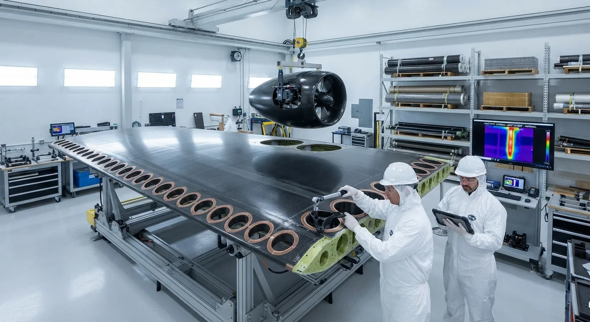
The wing of a DEP aircraft must simultaneously provide aerodynamic lift, house 12–20 electric propulsors, integrate cooling ducts for motor thermal management, and shield electromagnetic interference from high-voltage power cables. This multi-functional requirement is uniquely suited to carbon fiber composite design.
Table 2: Material Candidates for DEP Wing Primary Structure| Property | IM7/8552 Carbon/Epoxy | Aluminium 7075-T6 | Comparison |
| Tensile modulus (GPa) | 165 (0° UD) | 72 | 2.3× stiffer |
| Specific stiffness (GPa/(g/cm³)) | 105 | 26 | 4× higher |
| Fatigue limit at 10⁷ cycles (MPa) | 350 (0° UD) | 160 | 2.2× higher |
| CTE (ppm/°C) | −0.5 (0° UD) | 23 | Near-zero vs. high |
| Electrical conductivity (S/m) | 10²–10⁴ (with Cu mesh) | 3.5×10⁷ | Requires EMI mitigation |
| Thermal conductivity (W/m·K) | 5–50 (tailored layup) | 130–160 | Directionally tunable |
The near-zero CTE of carbon fiber is particularly valuable for DEP wings, where the precision mounting of electric motors requires dimensional stability across the operating temperature range (−55°C at cruise to +80°C at ground soak in desert conditions).
Nacelle and Pylon Integration
For DEP designs that mount propulsors on short pylons or integrated nacelles, carbon fiber enables:
Thermal Management Integration
Electric motors and inverters generate significant heat — up to 5–8 kW per propulsor unit. In a conventional metallic airframe, heat is conducted through aluminium structure to surface radiators. Carbon fiber's low through-thickness thermal conductivity (0.5–1.5 W/m·K) presents a challenge, addressed through:
- Embedded heat pipes: copper or aluminium heat pipes co-cured into CFRP laminates, achieving effective thermal conductivity of 200–600 W/m·K in-plane
- Through-thickness thermal vias: arrays of thermally conductive carbon fibre (pitch-based, 400–800 W/m·K K13D-type) oriented through the thickness
- Graphene-enhanced resin systems: 15–30% improvement in through-thickness conductivity with 1–3 wt% graphene nanoplatelet loading
- Liquid cooling channels: co-bonded titanium tubing integrated into the CFRP structure during cure
Electromagnetic Interference (EMI) Shielding
High-voltage power cables (800–1,200 V DC) running through DEP wings generate EM fields that can interfere with flight control systems. Unlike aluminium, which provides 60–80 dB of natural shielding, carbon fiber offers only 20–40 dB depending on fibre type and laminate architecture.
EMI mitigation strategies for CFRP DEP structures include:
Certification Considerations
Composite Airframe Certification for DEP
The certification of composite-intensive DEP airframes under EASA CS-25 / FAR Part 25 involves several unique considerations:
Current Development Programs
Key hybrid-electric DEP aircraft programs leveraging CFRP structures include:
- Heart Aerospace ES-30 (Sweden): 30-seat regional hybrid-electric, CFRP fuselage and wing, first flight 2026
- Ampaire Eco Otter (USA/Brazil): 9-seat hybrid-electric conversion, CFRP structural modifications to the DHC-6 Otter
- Elysian E9X (Netherlands): 90-seat fully electric, advanced CFRP airframe with 60% composite content
- Harbinger Technologies (USA): Retrofit hybrid-electric CFRP wing kit for existing 9,000 kg class aircraft
- Rolls-Royce ACCEL / Ion Bird (UK): Demonstration all-electric CFRP airframe, 480+ km/h record holder
FAQ
Q: How does the fatigue life of CFRP compare to aluminium under DEP vibration loading?
Carbon fiber composites demonstrate significantly superior fatigue performance in the high-cycle regime (10⁶–10⁷ cycles) characteristic of DEP vibratory loads. IM7/8552 carbon/epoxy retains 85–95% of its static strength after 10⁷ cycles, compared to 40–60% for 7075-T6 aluminium under equivalent stress ratios (R=0.1). The fibre-dominated fatigue response of unidirectional CFRP means that matrix cracks do not propagate into fibre failure until very high cycle counts, making CFRP inherently more tolerant of the 2,000–5,000 load cycles per flight typical of DEP operation.
Q: Can existing CFRP repair techniques be applied to hybrid-electric aircraft structures?
Existing bonded composite repair methods (scarf/bonded patch per AC 20-107B) are generally applicable to DEP airframe structures, but with important modifications. Repair zones near embedded thermal management features (heat pipes, cooling channels) require special assessment to ensure thermal function is restored. EMI shielding continuity must be verified after repair — copper foil grounding straps must be re-established across the repair boundary. Additionally, repair technicians require electrical safety training for working near high-voltage power distribution (800–1,200 V DC) during maintenance operations.
Q: What are the specific CFRP material qualifications needed for DEP airframe certification?
Composite materials for DEP primary structure must meet enhanced requirements beyond standard aerospace qualification (MMPDS-18 / CMH-17). Key additions include: through-thickness thermal conductivity measurement (ASTM E1461) for thermal management integration assessment, electrical resistivity testing (ASTM D4496) for EMI shielding verification, combined thermal-mechanical cycling (10³ cycles from −55°C to +80°C under 50% ultimate load), and DC voltage endurance testing (per ASTM D3755 for high-voltage insulation integrity at 5 kV/mm through-thickness).
YongXian CarbonFiber supplies aerospace-grade CFRP prepreg materials and custom structural components for hybrid-electric aircraft programs. Contact our aerospace engineering team for material qualification support and component design consultation.
Part of topic
Related Articles
- Carbon Fiber Mooring for Floating Offshore Wind: Fatigue and Corrosion in Deep Water
- Carbon Fiber Bicycle Frame Optimization: Layup Design and Manufacturing for Competitive Racing
- Carbon Fiber CFRP Retrofit for Infrastructure: Bridge and Building Seismic Strengthening
- Carbon Fiber Medical Imaging Equipment: Lightweight Gantry and Couch Structures for MRI/CT
- Carbon Fiber EV Battery Enclosures: Crash Safety and Electromagnetic Shielding Design
- Carbon Fiber Structures for Low-Altitude Economy: UAV Airframes and eVTOL Components
Interested in Our Products?
Contact our team for competitive pricing and technical specifications.
Get a QuoteRelated Products

Carbon fiber standard plate-3k stripe
Lightweight, ultra-rigid standard sheets for drone fuselages, robot housings, facades and structural applications.

Carbon Fiber Plate — 3K Twill T700 1.5mm
Thin 1.5mm carbon fiber plate with 3K twill weave surface. Lightweight and stiff, commonly used for covers, panels, drone bodies, and applications requiring a premium aesthetic appearance.

Square Carbon Fiber Tube — 3K Twill T700
Square cross-section carbon fiber tube manufactured with 3K twill weave for torsional strength. Preferred for structural frames, trusses, and support columns where rectangular geometry offers design flexibility.

Carbon Fiber Plate — 3K Twill T700 3.0mm
Medium-thickness 3.0mm carbon fiber plate offering significantly higher load capacity while maintaining attractive 3K twill finish. Suitable for structural brackets, reinforcement plates, and load-bearing panels.

Carbon Fiber Plate — UD Unidirectional T700
Unidirectional carbon fiber plate with all fibers oriented in a single direction for maximum strength along the fiber axis. Essential for structural reinforcements, splints, and applications where load direction is predictable.