
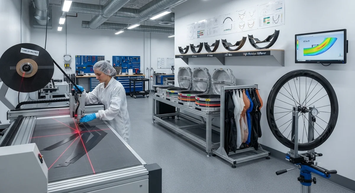
A deep technical dive into carbon fiber bicycle rim manufacturing — from prepreg layup and bladder molding to rim profile aerodynamics, brake track thermal management, and spoke bed engineering for high-performance road and track cycling.
Introduction: The Engineering Challenge of Carbon Fiber Rims
Carbon fiber bicycle wheel rims represent one of the most demanding applications of composite manufacturing in the sporting goods industry. A modern rim must simultaneously satisfy requirements for aerodynamic efficiency (drag reduction of 15–30% compared to box-section aluminium rims), lateral stiffness for sprint and cornering loads, radial compliance for rider comfort, brake track thermal resistance to withstand temperatures exceeding 220°C during prolonged descents, and a finished weight of 280–450 g per rim — all at a manufacturing cost that allows retail pricing between USD 600 and 3,500 per wheelset.
The carbon fibre rim market has grown at a CAGR of 14.3% from 2020 to 2025, driven by the global cycling boom and the increasing adoption of disc brakes — which removed the thermal constraints that previously limited rim depth to 50–60 mm on rim-brake wheels. Current production rims range from 25 mm shallow-section climbing rims to 80 mm deep-section aero rims, with the global market estimated at approximately 2.8 million rims manufactured in 2025, consuming roughly 1,200–1,500 metric tonnes of carbon fibre prepreg annually.
Manufacturing Processes
Prepreg Layup and Ply Scheduling
The vast majority of high-end carbon rims (85–90% by value) are manufactured using unidirectional (UD) carbon fibre prepreg, hand-laid or robotically placed into a two-part aluminium or steel mould. Ply schedules are proprietary to each rim manufacturer but follow a common architecture: a 0° hoop layer (fibres oriented circumferentially around the rim) for hoop strength and spoke bed load transfer; ±45° bias layers for torsion stiffness and impact resistance; and a 90° radial layer (fibres running radially across the rim cross-section) for lateral stiffness and brake track compaction.
Typical prepreg materials are high-modulus (HM) and intermediate-modulus (IM) carbon fibres in a toughened epoxy matrix. Toray T700S (standard modulus, 230 GPa) is widely used for the core structural plies, while Toray M40J (high modulus, 377 GPa), M46J (436 GPa), or Mitsubishi K63712 (pitch-based, 640 GPa) are used in select plies to increase rim stiffness without adding weight. The ratio of HM to IM fibres determines the rim's stiffness-to-weight ratio — a critical performance differentiator.
Table 1: Prepreg Ply Schedule for a 50 mm Deep-Section Aero Rim
| Ply Group | Fibre Orientation | Fibre Type | Areal Weight (g/m²) | Number of Plies | Function |
|---|---|---|---|---|---|
| Hoop (outer) | 0° (circumferential) | T700S | 200 | 2 | Spoke bed load distribution, impact resistance |
| Bias (outer) | ±45° | T700S | 150 | 2 | Torsion stiffness, brake track shear strength |
| Stiffener | 0° | M46J (HM) | 100 | 1 | Lateral stiffness improvement (+15–20%) |
| Core | 0°/90° fabric | T700S | 200 | 2 | Main structural core, radial strength |
| Bias (inner) | ±45° | T700S | 150 | 2 | Internal torsion, impact resistance |
| Hoop (inner) | 0° (circumferential) | T700S | 200 | 2 | Internal spoke bed reinforcement |
| Total plies | 11 | Cured ply thickness ~1.8–2.2 mm | |||
Bladder Molding vs. Compression Molding
Two primary molding methods dominate carbon rim production. Bladder molding — used by Zipp, ENVE, and Bontrager for their top-tier rims — involves laying prepreg into a rigid female mould cavity, inserting a silicone or thermoplastic bladder, closing the mould, and inflating the bladder to 6–10 bar while the mould is heated to 150–180°C. The bladder applies uniform pressure to the concave inner surface of the rim, producing excellent compaction at the brake track and spoke bed radii. Cycle time per rim is 20–35 minutes, limiting production to 2–3 rims per mould per hour.
Compression molding — used by Chinese OEM manufacturers for mid-range and entry-level rims — uses a matched male-female tool set. Prepreg is laid into the female cavity; the male plug is inserted; and the entire assembly is pressed in a hydraulic press at 50–150 tonnes. Compression molding offers faster cycle times (8–15 minutes) and lower tooling cost, but produces rims with higher void content (1.5–3.0% vs. 0.5–1.2% for bladder molding) and more variable compaction at the brake track — the most structurally critical zone of the rim.
Aerodynamic Design Optimization
Rim Profile and Airfoil Selection
The aerodynamic performance of a carbon rim is governed by its cross-sectional profile. Modern aero rims use truncated airfoil shapes developed from NACA 6-series and Selig-Donovan (SD) profiles, optimised for the Reynolds number regime experienced by bicycle wheels — typically Re = 1.5 × 10⁵ to 4.0 × 10⁵, corresponding to 30–60 km/h cycling speeds at sea level. The key geometric parameters are rim depth (D), maximum width (W), and the position of maximum width as a fraction of chord (X/C).
- Rim depth (D): Determines frontal area and thus potential drag reduction. Increasing rim depth from 30 mm to 50 mm reduces wheel drag by approximately 12–18% at 45 km/h in a zero-yaw condition. From 50 mm to 80 mm, the incremental drag reduction diminishes to 5–8%, while crosswind stability — measured as the yaw angle at which side force exceeds rider corrective capacity — decreases from 18° to 10°.
- Maximum width (W): The UCI legal limit for rim width at the brake track is 28 mm (disc brake rims are exempt). Wider rims (25–28 mm external width) allow the tyre to assume a more natural aerodynamic shape, reducing the tyre-rim transition turbulence. Computational fluid dynamics (CFD) analysis shows that increasing rim external width from 22 mm to 28 mm reduces total wheel-tyre system drag by 4–7% at 45 km/h.
- Position of maximum width (X/C): An X/C ratio of 0.40–0.50 (maximum width at 40–50% of chord from leading edge) produces the best balance of low drag and crosswind stability. Profiles with X/C > 0.55 are more stable in crosswinds but have 3–6% higher drag at zero yaw.
Table 2: Aerodynamic Performance Comparison — Rim Depth Scenarios
| Rim Depth | Width External | Drag at 45 km/h (0° yaw) | Drag at 45 km/h (10° yaw) | Crosswind Limit (yaw angle) | Rim Mass (g) | Typical Application |
|---|---|---|---|---|---|---|
| 25 mm | 22 mm | 4.8 N | 5.9 N | 22° | 290–320 | Climbing, mountain stages |
| 35 mm | 24 mm | 4.3 N | 5.4 N | 20° | 320–350 | All-rounder, entry-level aero |
| 50 mm | 26 mm | 3.9 N | 5.0 N | 17° | 360–400 | Road racing, criteriums |
| 65 mm | 27 mm | 3.7 N | 4.8 N | 13° | 390–440 | Time trial, triathlon |
| 80 mm | 28 mm | 3.6 N | 4.7 N | 10° | 420–480 | Track, velodrome pursuit |
Note: Drag values are per wheel, measured in wind tunnel at 45 km/h with a 25 mm Continental GP5000 tyre. Crosswind limit is the yaw angle at which steering torque exceeds 5 N·m.
Brake Track Engineering
For rim-brake carbon rims — still dominant in road racing and triathlon — the brake track is the most challenging engineering zone. During a 4 km descent at 8% gradient, brake track surface temperatures can reach 180–240°C, exceeding the glass transition temperature (Tg) of standard epoxy systems (150–180°C). Above Tg, the resin softens, leading to brake track deformation, delamination, and catastrophic rim failure.
Manufacturers employ several strategies to manage brake track heat: high-Tg resin systems (190–220°C, using BMI or modified epoxy); ceramic particle additives (silicon carbide or alumina, 5–15% by volume) in the outer brake ply to increase thermal conductivity and wear resistance; and heat-dissipating brake track inserts — aluminium or copper alloy sections co-cured into the rim to conduct heat away from the braking surface. Maximum brake track temperature in well-engineered rims is typically maintained below 170°C during extreme descent conditions.
Spoke Bed Design and Nipple Interface
The spoke bed — the interface between carbon rim and spoke nipple — must transfer spoke tension loads of 800–1,300 N per spoke (16–24 spokes per wheel) without localised deformation or fatigue failure. Three spoke bed architectures are in production: drilled metal eyelets (aluminium or brass) embedded in the rim during molding, offering the best fatigue life (100,000+ km) but adding 35–55 g per rim; moulded-in spoke holes with no eyelet, saving weight (15–25 g) but requiring careful stress distribution analysis; and external spoke bed reinforcement plates — a hybrid approach where a thin carbon plate is bonded over the spoke bed zone to distribute nipple loads over a larger area.
Frequently Asked Questions
Q: What is the difference between low-modulus and high-modulus carbon fibre in rims?
A: Low-modulus (standard modulus, 220–250 GPa) fibres — T700S, T800S — are used for the bulk structural plies where impact resistance and damage tolerance are critical. High-modulus fibres (350–640 GPa) — M40J, M46J, K63712 — are used in selective stiffener plies to increase lateral stiffness (the rim's resistance to side-to-side flex under cornering loads). A rim using 100% HM fibre would be laterally stiff but brittle and susceptible to impact fracture. The optimal ratio is typically 15–30% HM plies by fibre mass, giving a 15–25% increase in lateral stiffness over an all-IM rim without a significant weight penalty.
Q: Are carbon rims with disc brakes safer than rim-brake carbon rims?
A: From a thermal perspective, yes. Disc brakes transfer braking heat to the rotor and hub — not the rim — eliminating the brake track overheating risk entirely. This allows rim manufacturers to use lower-Tg resin systems for weight savings, optimise the rim cross-section without brake track constraints (producing faster aerodynamic profiles), and reduce rim wall thickness at the brake zone from 1.8–2.5 mm to 1.2–1.6 mm, saving 40–70 g per rim. However, disc brake wheels are heavier overall (rotors + hub + spokes add 200–350 g per wheelset), and the aerodynamic benefit of thinner rims is partially offset by the rotor's drag contribution (approximately 0.2–0.4 N per rotor at 45 km/h).
Q: How are carbon rims tested for structural integrity?
A: Rim manufacturers follow the ISO 4210 safety standard for bicycle testing, which requires impact testing (a 22.5 kg mass dropped from 40 mm onto the rim-spoke assembly) and fatigue testing (10,000 cycles of radial load and 50,000 cycles of lateral load at 120% of maximum rider + bicycle weight). High-end rims are additionally tested to the German DIN PLUS standard, which includes a 50% higher impact energy (22.5 kg from 60 mm) and combined thermal-mechanical cycling (brake track heated to 160°C while under lateral load). Most manufacturers also perform burst testing — pressurising the rim-tyre assembly to 3–4× the maximum rated tyre pressure to verify failure margin.
Q: Can carbon rims be repaired after crash damage?
A: Small cosmetic damage (surface scratches, paint chips) does not affect structural integrity. Cracks, delamination, or deformation require professional assessment. Repairable damage — typically limited to spoke bed cracks, brake track surface delamination under 10 mm diameter, or impact damage confined to a single 50 mm section — can be repaired by certified composite repair shops using wet layup or prepreg patches, vacuum bag curing, and ultrasonic C-scan verification. Non-repairable damage includes full hoop cracks, brake track deformation beyond 0.5 mm radial runout, or any damage extending through the entire rim wall thickness. Repaired rims should never be used at the front wheel position and should be derated to 80% of the original maximum rider weight specification.
Q: What manufacturing defects are most common in carbon rims?
A: Production QC data from three large rim OEM facilities (2024–2025) identifies the following defect distribution: brake track porosity/voids (28% of defects), asymmetric spoke hole positioning (22%), brake track surface waviness (18%), incorrect ply orientation (12%), resin-rich or resin-starved zones at the spoke bed edge (10%), and foreign inclusion (5%). The remaining 5% comprises mould damage, incorrect curing temperature profile, and bladder rupture. Overall first-pass yield for high-end bladder-molded rims is 85–92%; for compression-molded rims, 72–82%. Post-mold inspection includes 100% visual inspection, C-scan ultrasonic testing on a sampling basis (10–30% of production), and spoke bed pull-out testing (ASTM D7332) on each batch.
Conclusion
Carbon fibre bicycle wheel rim manufacturing is a mature yet continuously evolving technology domain, where incremental improvements in prepreg architecture, molding process control, aerodynamic profile design, and thermal management translate directly into measurable performance gains for the end user. The transition from rim brakes to disc brakes has removed the single greatest engineering constraint on rim design, enabling deeper profiles, thinner wall sections, and lower weights. At the same time, the increasing accessibility of computational fluid dynamics, finite element analysis, and process simulation tools has flattened the technology curve, allowing smaller manufacturers to compete with established brands on aero performance and structural reliability. For OEM buyers, the key differentiators remain process quality — bladder molding vs. compression molding yields a demonstrable difference in void content and brake track integrity — and fibre specification transparency. YongXian CarbonFiber supplies UD prepreg and woven fabric solutions optimised for bicycle rim applications, including high-Tg brake track epoxy systems and hybrid HM/IM ply architectures. Contact our composites engineering team for material qualification support and custom ply schedule development for your rim production program.
Part of topic
Related Articles
- Carbon Fiber Mooring for Floating Offshore Wind: Fatigue and Corrosion in Deep Water
- Carbon Fiber Bicycle Frame Optimization: Layup Design and Manufacturing for Competitive Racing
- Carbon Fiber CFRP Retrofit for Infrastructure: Bridge and Building Seismic Strengthening
- Carbon Fiber Medical Imaging Equipment: Lightweight Gantry and Couch Structures for MRI/CT
- Carbon Fiber EV Battery Enclosures: Crash Safety and Electromagnetic Shielding Design
- Carbon Fiber Structures for Low-Altitude Economy: UAV Airframes and eVTOL Components
Interested in Our Products?
Contact our team for competitive pricing and technical specifications.
Get a QuoteRelated Products

Carbon fiber standard plate-3k stripe
Lightweight, ultra-rigid standard sheets for drone fuselages, robot housings, facades and structural applications.

Carbon Fiber Plate — 3K Twill T700 1.5mm
Thin 1.5mm carbon fiber plate with 3K twill weave surface. Lightweight and stiff, commonly used for covers, panels, drone bodies, and applications requiring a premium aesthetic appearance.

Square Carbon Fiber Tube — 3K Twill T700
Square cross-section carbon fiber tube manufactured with 3K twill weave for torsional strength. Preferred for structural frames, trusses, and support columns where rectangular geometry offers design flexibility.

Carbon Fiber Plate — 3K Twill T700 3.0mm
Medium-thickness 3.0mm carbon fiber plate offering significantly higher load capacity while maintaining attractive 3K twill finish. Suitable for structural brackets, reinforcement plates, and load-bearing panels.

Carbon Fiber Plate — UD Unidirectional T700
Unidirectional carbon fiber plate with all fibers oriented in a single direction for maximum strength along the fiber axis. Essential for structural reinforcements, splints, and applications where load direction is predictable.