
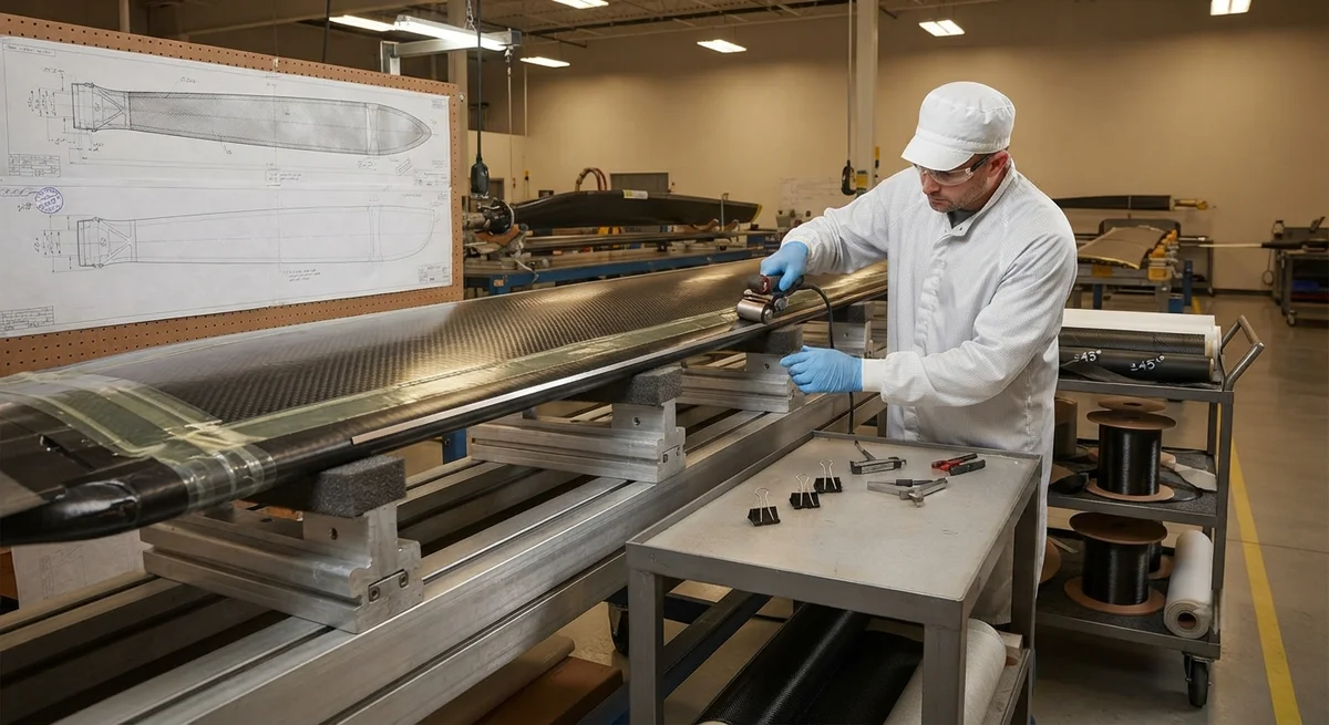
A helicopter main rotor blade is engineering's most demanding rotating structure. Each blade is a cantilever beam that must carry the aircraft's full lift, absorb flight and gust loads, and endure millions of tension, bending, and vibration cycles every year. Unlike a fixed-wing wing, a
Introduction
A helicopter main rotor blade is engineering's most demanding rotating structure. Each blade is a cantilever beam that must carry the aircraft's full lift, absorb flight and gust loads, and endure millions of tension, bending, and vibration cycles every year. Unlike a fixed-wing wing, a rotor blade sees the aerodynamic load reverse in each revolution, and it operates within a few millimeters of the aircraft's own wake on every pass. The result is a fatigue environment so severe that blade life, not strength, has historically governed rotorcraft maintenance and cost.
Carbon fiber composites transformed this problem. Where metal rotor blades were limited by the fatigue endurance of aluminum or steel, carbon fiber offers roughly two to four times the fatigue endurance limit of aluminum on a specific-strength basis, together with the ability to tailor stiffness along the blade to control vibration and stall margin. Modern civil helicopters from Airbus and Bell, and military rotorcraft such as the Boeing AH-64 and variants, fly on composite main rotor blades that trace their load path through a single load-bearing structure: the spar. This article examines how that carbon fiber spar is designed, how the blade survives leading-edge erosion, and how fatigue life is demonstrated in qualification.
Blade Architecture: Spar, Skin, and Core
A modern carbon fiber main rotor blade is a three-part structure built around a primary load-bearing member:
- The spar: The spar is the structural backbone that occupies the leading portion of the airfoil. In modern blades it is usually a single large carbon fiber spar — formed as a woven or unidirectional "D-spar" — that carries the centrifugal tension, flap bending, and edgewise bending loads. The spar concentrates the material where it works hardest and defines the blade's structural life.
- The skin: A thin carbon fiber or hybrid (carbon/glass) skin covers the upper and lower surfaces behind the spar to complete the aerodynamic shape. It transfers aerodynamic pressure into the spar and contributes to torsion stiffness through closure of the closed section.
- The core: A lightweight foam or honeycomb core fills the trailing-edge region behind the spar. It stabilizes the thin skin against buckling, absorbs impact, and keeps the blade light by replacing solid material with a low-density filler.
The D-spar is the key innovation. Early rotorcraft used a solid-steel or layered spar; modern design forms a single continuous carbon fiber D-spar that runs tip to root, with the blade's skin and trailing-edge core bonded behind it. Because the spar is a closed, continuous member, it provides both the flap stiffness and the torsion stiffness the blade needs, while stress concentrations at bolt holes and transitions are moved to the relatively benign root end where the blade is thickest.
Spar Design and Load Path
Designing the carbon fiber spar is a matter of managing four load types and their directions, summarized below:
| Load Type | Direction | Primary Structure | Key Design Concern |
|---|---|---|---|
| Centrifugal tension | Spanwise (root direction) | Spar axes | Holds blades against rotation; sets root attachment sizing |
| Flap bending | Out of plane | Spar cap | Dominant fatigue driver; controls blade life |
| Edgewise (lead-lag) bending | In plane | Spar web/cap | In-plane resonance and damping control |
| Torsion | Twist direction | Closed spar section + skin | Pitch control authority and aeroelastic stability |
Carbon fiber spar construction balances stiffness tailoring against manufacturing cost. Unidirectional tape is laid along the span to carry tension and bending; ±45° plies are added at the web to carry torsion and shear. Fibers run predominantly in the spanwise direction, but a carefully defined off-axis fraction controls the edgewise mode and prevents flutter. A typical spar layup might be 60% spanwise (0°) plies and 40% ±45° plies, tuned by stiffness targets and aeroelastic analysis. This tailoring lets engineers place the blade's natural frequencies away from harmonics of the rotor speed, which is the central anti-resonance task in rotor design.
Leading-Edge Erosion Protection
The blade's leading edge is its most vulnerable surface. At tip speeds of 200-240 m/s, rain, sand, and dust erode the edge at a rate that, unprotected, would remove material over months of operation. Because the erosion degrades the airfoil and exposes the carbon fiber spar, protection is mandatory. Three erosion protection systems dominate:
- Polyurethane (PU) coating: A sprayed-on abrasion-resistant polyurethane provides a low-cost baseline. It is applied over the leading edge and re-applied at intervals, absorbing rain erosion through elastic deformation. It suits low-to-medium erosion environments and soft rotorcraft (turbine, low sand).
- Nickel or titanium erosion shields: A leading-edge metal strip (typically ~0.4-0.8 mm nickel or titanium) is bonded or dovetailed onto the composite edge. Metal shields handle the most abrasive environments — military tactical helicopters, desert and carrier operations — providing many times the life of PU. Titanium is preferred in very harsh conditions for its corrosion and fatigue resistance.
- Polyurethane tape: A replaceable PU tape provides rapid field replacement of a worn edge without a paint shop. It is common as a re-coating regime on civil machines and as a sacrificial layer over metal shields.
Any erosion shield must be bonded so that it does not create a stress raiser at the transition into the composite edge, and it must survive the blade's centrifugal strain without detaching. The edge thickness, shield bond line control, and the transition overlay all influence fatigue performance at what is otherwise the highest-strain region of the blade.
Fatigue Life and Damage Tolerance
Fatigue life is the defining certification metric for a rotor blade. Carbon fiber offers a major advantage over metal: a very flat S-N curve. Where aluminum's fatigue strength falls sharply with cycle count, carbon fiber retains a high fraction of its static strength past 10 million cycles. This flattens the design allowable curve and lets a carbon fiber blade carry a much lower fatigue knock-down than metal, extending both the safe-life limit and the inspection interval.
Damage tolerance is equally important. A composite blade is designed so that visible damage — a laceration in the skin, a delamination patch, a small tip erosion notch — has a defined inspection interval before it could reduce residual strength below certification limits. This damage-tolerant design, documented through repeated tests of impact-damaged specimens and verified in the fleet, allows operators to fly a blade to its inspection interval with confidence. The result is a blade that is both longevity-forward and inspectable, in contrast to metal blades whose crack-free condition must be confirmed by frequent inspection.
Qualification for Civil and Military Rotorcraft
Rotary-wing certification is rigorous because the rotor is the sole lift and control system — a failure is not survivable. Qualification for a composite main rotor blade includes all of the following:
- Static strength: Proof that the blade, spar, and root attachment withstand design ultimate loads including overspeed and limit gust conditions, held for defined durations.
- Fatigue testing: Full-scale blade(s) are loaded through flight-load spectra until failure or to a target number of lifetimes (often 2-5 test lifetimes for civil, higher for military), with development of an S-N curve for the spar.
- Damage tolerance and impact: Specimens with simulated impact damage, surface cuts, and erosion are tested to show residual strength stays above requirements through the inspection interval.
- Erosion and environmental: Rain, sand, and artificial-dust erosion tests quantify shield life, and hot/wet and cold conditioning confirm the resin system performs across the temperature envelope.
- Lightning: Blades are strikes on a rotorcraft on a per-year basis; the blade must carry attachment currents without loss of structural integrity or a hazard to the airframe.
For military rotorcraft, additional proof includes ballistic tolerance, operability from austere/high-sand environments, and expeditionary repairability of the composite structure under field conditions.
Frequently Asked Questions
Why is carbon fiber better than aluminum or steel for a rotor blade spar?
Carbon fiber offers roughly two to four times the fatigue endurance limit of aluminum on a specific-strength basis, meaning a carbon fiber spar can be lighter yet survive the same number of load cycles. Combined with the ability to tailor stiffness along the blade, this allows designers to place natural frequencies away from rotor-speed harmonics and reduce vibration. Carbon fiber also resists corrosion and can be formed into a single continuous D-spar, eliminating the mechanical joints that create stress concentrators in metal blades.
How does the D-spar improve a rotor blade compared with older designs?
The D-spar is a single closed, continuous carbon fiber member running from root to tip along the leading edge. Because it is closed and continuous, it provides both flap bending stiffness and torsion stiffness in one part, with no mechanical joint between the two. Older blades used separate metal spars with bolts or layered construction, which concentrated stress at joints and holes. The D-spar moves connections to the thick, benign root end, simplifies assembly, and reduces the stress concentrations that governed metal blade life.
How does a composite rotor blade resist leading-edge erosion and how is the shield replaced?
Protection is layered. A polyurethane coating or tape provides a replaceable baseline that absorbs rain erosion elastically; at higher erosion, a bonded nickel or titanium shield (about 0.4-0.8 mm thick) is applied to the leading edge and lasts many times longer than PU. The shield is bonded with controlled bond-line thickness to avoid a stress raiser at the transition into the composite, and it must survive the centrifugal strain without detaching. Worn PU tape can be replaced in the field, while a worn metal shield is re-bonded at a maintenance facility.
How long does a carbon fiber main rotor blade last?
A carbon fiber blade is typically designed to a safe fatigue life measured in years of operation, often with an on-maintenance inspection interval instead of a hard life limit. Because carbon fiber's S-N curve is flat, the blade can retain much of its static strength past 10 million cycles, and damage-tolerant design sets inspection intervals that keep residual strength above certification limits even with visible damage present. Blade life is therefore managed through condition monitoring and scheduled inspection rather than a fixed calendar life, and composite blades routinely outlast their metal predecessors.
Conclusion
Carbon fiber helicopter main rotor blades are among the clearest demonstrations of what composites deliver in rotating aerospace structures: the fatigue endurance, stiffness tailoring, and damage tolerance that modern civil and military rotorcraft rely on. The single continuous D-spar concentrates the load path and moves connections to the benign root; lightweight skins and cores complete the airfoil; and layered erosion protection — polyurethane, then metal shields — keeps the fatigue-critical leading edge intact for years. The result is a blade with a longer safe life and a shorter inspection burden than the metal blades it replaced.
For rotorcraft programs and blade suppliers, the practical decisions are spar layup and stiffness tailoring, erosion shield selection for the operating environment, and fatigue/damage-tolerance test programs. Explore our unidirectional and woven carbon fiber spars and reinforcement materials for rotor blade applications, or contact our engineering team to discuss material selection and fatigue qualification for your rotor program.
Part of topic
Related Articles
- Carbon Fiber Tube for Sale: Comparing Listings and Avoiding Bad Specs
- Carbon Fiber Engine Parts: High-Temperature Performance for Racing and Performance Vehicles
- Carbon Fiber Body Parts: Automotive Exterior Panels and Structural Components
- Carbon Fiber Drone Body Manufacturing: Monocoque Design and Production Methods
- Carbon Fiber Drone Parts Supplier: FPV Frames, Arms and Structural Components
- Filament Wound Epoxy Tubes: Industrial Applications from Oil and Gas to Aerospace
Interested in Our Products?
Contact our team for competitive pricing and technical specifications.
Get a QuoteRelated Products

Carbon fiber standard plate-3k stripe
Lightweight, ultra-rigid standard sheets for drone fuselages, robot housings, facades and structural applications.

Carbon Fiber Plate — 3K Twill T700 3.0mm
Medium-thickness 3.0mm carbon fiber plate offering significantly higher load capacity while maintaining attractive 3K twill finish. Suitable for structural brackets, reinforcement plates, and load-bearing panels.

Carbon Fiber Plate — 3K Twill T700 1.5mm
Thin 1.5mm carbon fiber plate with 3K twill weave surface. Lightweight and stiff, commonly used for covers, panels, drone bodies, and applications requiring a premium aesthetic appearance.

Square Carbon Fiber Tube — 3K Twill T700
Square cross-section carbon fiber tube manufactured with 3K twill weave for torsional strength. Preferred for structural frames, trusses, and support columns where rectangular geometry offers design flexibility.

Carbon Fiber Plate — UD Unidirectional T700
Unidirectional carbon fiber plate with all fibers oriented in a single direction for maximum strength along the fiber axis. Essential for structural reinforcements, splints, and applications where load direction is predictable.