
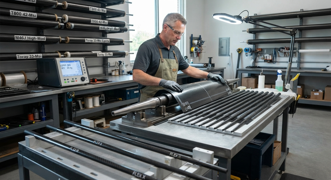
Precision manufacturing analysis of carbon fiber golf shafts: dimensional tolerances, torque control (1.5–7.0° range), flex profile validation (CPM to ±3), and defect types with rejection criteria.
Introduction: Precision Engineering in Carbon Fiber Golf Shafts
The modern carbon fiber golf shaft is a highly engineered structural component that directly influences swing speed, launch angle, spin rate, and shot dispersion. Unlike steel shafts, where material properties are relatively uniform, carbon fiber shafts derive their performance characteristics from precise control over fiber orientation, resin chemistry, ply stacking sequence, and curing parameters. In a market valued at $1.8 billion globally for golf shafts (2025), carbon fiber accounts for over 70% of all shafts sold on the US PGA Tour and approximately 55% of the global aftermarket. Manufacturing tolerance — the allowable deviation from designed specifications — determines whether a shaft performs as intended or introduces unpredictable variability into a golfer's game.
Critical Tolerances in Carbon Fiber Shaft Manufacturing
The manufacturing process for carbon fiber golf shafts involves roll-wrapping preimpregnated (prepreg) unidirectional carbon fiber sheets around a tapered steel mandrel, followed by compression molding at elevated temperature and pressure. Each step introduces potential dimensional and material variations that must be controlled within tight manufacturing tolerances.
Key Dimensional Tolerances
| Parameter | Typical Specification | Premium Tolerance (±) | Standard Tolerance (±) | Measurement Method |
|---|---|---|---|---|
| Total weight (uncut, 46") | 50–85 g | ±0.5 g | ±1.5 g | Digital scale, 0.01 g resolution |
| Shaft outer diameter at butt | 0.600" (15.24 mm) | ±0.002" (0.05 mm) | ±0.005" (0.13 mm) | Laser micrometer |
| Shaft OD at tip (0.5" from end) | 0.335" (8.51 mm) | ±0.0015" (0.038 mm) | ±0.003" (0.076 mm) | Air gauge |
| Wall thickness (mid-section) | 0.030–0.045" (0.76–1.14 mm) | ±0.0015" (0.038 mm) | ±0.003" (0.076 mm) | Ultrasonic thickness gauge |
| Straightness deviation | < 0.3 mm over 1,200 mm | ≤ 0.15 mm | ≤ 0.5 mm | Rotary straightness fixture |
| Concentricity | ≥ 92% | ≥ 95% | ≥ 90% | X-ray or CT scan |
| Spline (alignment mark) angle | Reference 0° | ±2° | ±5° | Vision system |
Torque: Definition and Control
Torque, measured in degrees, describes the shaft's rotational resistance under an applied torsional load. It is a critical performance parameter because it directly affects how much the clubface rotates during impact — a key determinant of directional accuracy. Lower torque (1.5–3.0°) produces a stiffer feel and tighter shot dispersion, favored by low-handicap and professional players. Higher torque (4.5–7.0°) provides more feel and feedback, preferred by recreational golfers.
Torque is controlled by the fiber orientation in the shaft's intermediate layers. A shaft's torque value is primarily determined by the ±45° plies: increasing the proportion of off-axis fibers (particularly +45°/−45° layers) in the 40–60% range of total laminate thickness reduces torque proportionally. Typical torque tolerances in production are ±0.3° for premium shafts and ±0.5° for standard models.
Flex Profile Quality Control
The flex profile — the stiffness distribution along the shaft length — is arguably the most important performance characteristic. Unlike steel shafts, where flex is relatively linear from butt to tip, carbon fiber shafts can be engineered with multiple stiffness zones to optimize launch conditions. A typical triple-zone profile includes:
- Butt section (0–12" from grip end): Stiffness 180–250 N/mm — controls overall feel and directional stability; stiffer in X-flex, softer in L/A-flex
- Mid section (12–30"): Stiffness 140–200 N/mm — the transition zone that influences kick point and energy transfer; a stiffer mid-section lowers the kick point, producing a higher launch
- Tip section (30–46"): Stiffness 100–160 N/mm — the most critical zone; tip flexibility directly affects launch angle and spin; 55% of flex profile variation between flex grades occurs in this region
Flex profile consistency is measured using a frequency analyzer (CPM — cycles per minute) or a 3-point bending stiffness profiler. A premium shaft lot maintains CPM variation of ≤ 3 CPM across 50+ sample shafts. Standard production accepts ≤ 5 CPM variation. Beyond CPM, full-field bending stiffness profiling (every 25 mm along the shaft) is increasingly adopted by Fujikura, Mitsubishi Chemical, and Graphite Design to characterize and control the complete flex curve.
Defect Types and Rejection Criteria
| Defect Type | Cause | Inspection Method | Acceptable Rate | Rejection Threshold |
|---|---|---|---|---|
| Porosity / voids in laminate | Insufficient consolidation pressure or resin starvation | Ultrasonic C-scan | < 1.5% void fraction | > 2.0% or any cluster > 1 mm |
| Fiber waviness / kink bands | Mandrel misalignment or prepreg wrinkling | Microscopy (20×) on cross-section | 0 (zero-tolerance) | Any visible waviness > 3 fiber diameters |
| Out-of-round cross-section | Uneven wrap tension or mold wear | Rotating laser profilometer | Ovality < 0.004" | Ovality > 0.006" |
| Surface blister / delamination | Moisture in prepreg or rapid pressure release | Visual + tap test | 0 (zero-tolerance) | Any visible delamination |
| Weight deviation outside spec | Resin content variation or off-weight prepreg lot | Weigh station at 46" length | ±1.5 g (Std), ±0.5 g (Prem) | Outside tolerance band |
| CPM deviation (soft/hard flex) | Cure temperature gradient or uneven layer count | Frequency analyzer | ±3 CPM (Prem), ±5 CPM (Std) | ±6 CPM or more |
Material Variability: Prepreg Quality Control
Carbon fiber prepreg — the intermediate material from which shafts are roll-wrapped — is itself a source of manufacturing variation. Key prepreg quality parameters affecting shaft consistency:
- Resin content tolerance: ±1.5% by weight (target 33–38% for golf shaft formulations); higher resin = heavier shaft with softer flex
- Tack (surface stickiness): Must be consistent within ±10% across roll length for uniform wrap adhesion
- Fiber aerial weight: ±3 g/m² for unidirectional prepreg (typical 100–150 g/m²); variation shifts final shaft weight and stiffness
- Gel time at 140°C: 180 ± 30 seconds — shorter gel time risks incomplete flow and void formation
Industry Standards and Testing Protocols
The golf shaft industry operates under several consensus standards developed by the USGA/R&A and industry bodies. Key tests include the frequency (CPM) test per ASTM D4475, the 3-point bend test per ASTM D790, and the torsional stiffness test (torque) per SGEF-001. Shaft manufacturers typically test 100% of production on a weight sorting line, with statistical process control (SPC) on CPM and torque using X̄-R control charts. Lot acceptance sampling per AQL 1.0 is standard for visual and dimensional inspection. Premium brands (Fujikura Ventus, Mitsubishi Tensei, Graphite Design Tour AD) additionally perform 100% CPM sorting and bin shafts into ±1 CPM sub-lots for tour-level consistency.
FAQ — Carbon Fiber Golf Shaft Manufacturing
Why do carbon fiber shafts have weight tolerances while steel shafts do not?
Steel shafts are drawn from seamless tubing with highly uniform wall thickness (tolerance ±0.001" or 0.025 mm), resulting in weight variation of only ±0.3 g for a 100 g shaft. Carbon fiber shafts are built up layer by layer from prepreg sheets; each layer introduces potential variation in resin content, fiber alignment, and consolidation. Even with tight process control, a 65 g carbon fiber shaft typically varies ±1.0–1.5 g between production runs. This inherent variability is why shaft model matching (buying two shafts from the same production lot, usually within 10 serial numbers) is recommended for serious players.
How do manufacturers achieve ±0.5 g weight tolerance on premium shafts?
Premium tolerance is achieved through three complementary strategies: (1) robotic prepreg cutting and layup to eliminate operator-induced ply alignment variation (manual cutting introduces ±0.3 mm overlap error per ply), (2) real-time resin flow monitoring during compression molding using dielectric sensors that detect cure completion within ±15 seconds, and (3) post-cure mass sorting: every shaft is weighed and digitally grouped into ±0.5 g bins. Shafts in the same weight bin are paired for matched set builds. Leading manufacturers report that only 55–65% of production falls within ±0.5 g of target; the remainder is downgraded to standard-tolerance product or used for flex-binned practice clubs.
What is the relationship between torque and shot dispersion?
Independent testing by Golf Laboratories (2024) measured the effect of torque on shot dispersion using a robot swing robot at 95 mph clubhead speed. For a 6-iron with a 2.0° torque shaft, the lateral dispersion was ±4.2 yards off-center. With a 5.0° torque shaft (same head, same swing), dispersion widened to ±8.9 yards — more than double. The mechanism is straightforward: higher torque allows more clubface rotation during the millisecond of ball contact, converting small swing path variations into larger face angle deviations. For this reason, tour players overwhelmingly select shafts in the 1.5–3.0° torque range. It should be noted, however, that torque interacts with player swing tempo — smooth swingers tolerate higher torque better than aggressive transition players.
How is the flex profile verified in production?
Production verification uses a multi-step approach. First, every shaft is frequency tested (CPM): the shaft is clamped at the butt with a known tip weight, vibrated, and its natural frequency recorded. CPM correlates strongly with overall flex feel. Second, a statistically sampled subset (typically 5–10%) undergoes full 3-point bending profiling: stiffness is measured at 25 mm intervals along the shaft length using a specialized flex profiler (e.g., Fujikura's proprietary FLEXPRO or the industry-standard FCM frequency analyzer). The resulting stiffness curve is compared against the design master curve; deviations exceeding ±5% at any measurement point trigger process adjustment. Premium manufacturers additionally use modal analysis (vibration mode shape) to validate that the shaft's dynamic bending behavior matches the designed flex profile.
Part of topic
Related Articles
- Carbon Fiber Mooring for Floating Offshore Wind: Fatigue and Corrosion in Deep Water
- Carbon Fiber Bicycle Frame Optimization: Layup Design and Manufacturing for Competitive Racing
- Carbon Fiber CFRP Retrofit for Infrastructure: Bridge and Building Seismic Strengthening
- Carbon Fiber Medical Imaging Equipment: Lightweight Gantry and Couch Structures for MRI/CT
- Carbon Fiber EV Battery Enclosures: Crash Safety and Electromagnetic Shielding Design
- Carbon Fiber Structures for Low-Altitude Economy: UAV Airframes and eVTOL Components
Interested in Our Products?
Contact our team for competitive pricing and technical specifications.
Get a QuoteRelated Products

Carbon fiber standard plate-3k stripe
Lightweight, ultra-rigid standard sheets for drone fuselages, robot housings, facades and structural applications.

Square Carbon Fiber Tube — 3K Twill T700
Square cross-section carbon fiber tube manufactured with 3K twill weave for torsional strength. Preferred for structural frames, trusses, and support columns where rectangular geometry offers design flexibility.

Carbon Fiber Plate — 3K Twill T700 3.0mm
Medium-thickness 3.0mm carbon fiber plate offering significantly higher load capacity while maintaining attractive 3K twill finish. Suitable for structural brackets, reinforcement plates, and load-bearing panels.

Carbon Fiber Plate — 3K Twill T700 1.5mm
Thin 1.5mm carbon fiber plate with 3K twill weave surface. Lightweight and stiff, commonly used for covers, panels, drone bodies, and applications requiring a premium aesthetic appearance.

Carbon Fiber Plate — UD Unidirectional T700
Unidirectional carbon fiber plate with all fibers oriented in a single direction for maximum strength along the fiber axis. Essential for structural reinforcements, splints, and applications where load direction is predictable.