
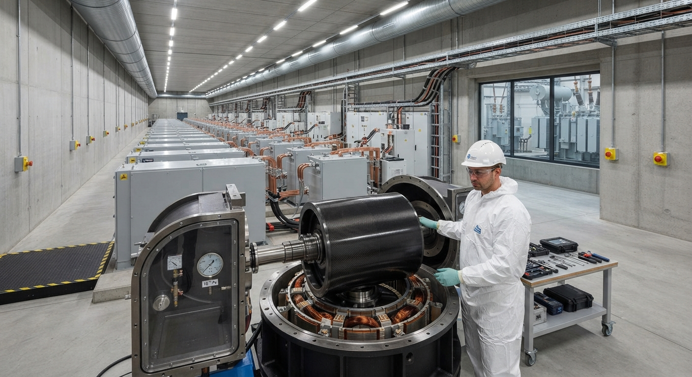
A comprehensive B2B technical analysis of carbon fiber composite flywheel rotors for grid-scale energy storage. This article covers rotor design principles, composite material selection for high-speed rotation, safety containment strategies, magnetic bearing systems, power electronics integration, a
Introduction
Grid-scale energy storage has emerged as a critical enabler for renewable energy integration, providing frequency regulation, voltage support, and arbitrage services that balance the intermittency of wind and solar generation. Among the competing storage technologies, flywheel energy storage systems (FESS) offer unique advantages in cycle life, power density, and environmental sustainability that complement electrochemical battery systems. The performance and economic viability of modern FESS are fundamentally dependent on the rotor material — and high-strength carbon fiber composites have become the enabling technology for the high peripheral speeds required to achieve commercially viable energy densities.
A flywheel stores kinetic energy as rotational motion, with stored energy proportional to the moment of inertia and the square of rotational speed. For a given rotor geometry, doubling the rotational speed quadruples the stored energy. This relationship creates a powerful incentive to maximize rotational speed, which in turn demands rotor materials with the highest possible specific strength (strength-to-density ratio). Carbon fiber reinforced polymer (CFRP) composites, with specific strengths 5–10 times greater than high-strength steel and 3–5 times greater than aluminum alloys, are the only materials capable of sustaining the hoop stresses at peripheral speeds exceeding 600 m/s required for competitive grid-scale flywheel systems.
This article provides a technical examination of CFRP flywheel rotor design for grid-scale applications, drawing on data from operating installations including Beacon Power's 20 MW Stephentown facility, Amber Kinetics' 32 kWh units, and next-generation 500 kWh-class systems currently in development.
| Parameter | Steel Rotor | CFRP Rotor (T700/Epoxy) | CFRP Rotor (M60J/Epoxy) | Unit |
|---|---|---|---|---|
| Tensile strength (hoop direction) | 1,200–1,800 | 2,500–3,500 | 3,800–4,800 | MPa |
| Density | 7.85 | 1.55–1.60 | 1.55–1.60 | g/cm³ |
| Specific strength | 153–229 | 1,563–2,258 | 2,375–3,097 | MPa/(g/cm³) |
| Max peripheral speed achievable | 350–500 | 750–950 | 950–1,200 | m/s |
| Energy density (rotor only) | 5–15 | 60–120 | 90–180 | Wh/kg |
| Cycle life (to 80% remaining strength) | 10⁵–10⁶ | 10⁶–10⁷ | 10⁶–10⁷ | cycles |
| Thermal conductivity (radial) | 45–55 | 0.5–1.5 | 0.5–1.5 | W/m·K |
| Steel containment mass multiplier | 1.0 (monolithic) | 2.5–4.0 | 2.5–4.0 | ratio |
| Raw material cost | $2–$8 | $40–$120 | $150–$400 | $/kg |
| Manufacturing complexity | Low (forged/machined) | High (filament wound) | High (filament wound) | — |
Rotor Design Principles for High-Speed CFRP Flywheels
The fundamental design challenge for CFRP flywheel rotors is managing the three-dimensional stress state that develops at high rotational speeds. At peripheral speeds of 800–1,000 m/s, the hoop stress in the composite can exceed 2.5 GPa — a regime where only high-modulus, high-strength carbon fibers with careful laminate design can operate reliably over millions of cycles. The radial stress, which in a monolithic metallic rotor is compressive, becomes tensile in a thick-walled composite rotor due to the anisotropy of the material properties combined with the Poisson effect along the fiber direction.
Three dominant rotor architectures have been developed for CFRP flywheel systems:
- Cylindrical hoop-wound rotor: The most mature design, used in Beacon Power's 100 kWh-class systems. Fibers are wound predominantly in the circumferential (hoop) direction at 85–90% volume fraction in a thin-walled cylinder geometry with a wall thickness-to-radius ratio (t/R) of 0.08–0.15. The rotor operates at peripheral speeds of 650–780 m/s, achieving energy densities of 60–80 Wh/kg. The primary advantage is manufacturing simplicity — the mandrel-wound cylinder can be produced on conventional filament winding equipment. The disadvantage is poor utilization of the interior volume, requiring a separate metallic hub for shaft attachment.
- Conical multi-ring interference-fit rotor: Designed to address the radial tensile stress limitation, this architecture consists of 3–6 concentric rings, each with a progressively thicker cross-section toward the outer radius. The rings are assembled with a calculated interference fit such that the outer rings pre-compress the inner rings, offsetting the tensile radial stresses that develop during rotation. Each ring is filament-wound at a precise hoop-to-radial thickness ratio optimized through finite element analysis. Amber Kinetics uses a variant of this design in its 32 kWh commercial units, achieving 850 m/s peripheral speed and 110 Wh/kg energy density. The manufacturing process requires precision grinding of each ring's inner and outer diameters to tolerances of ±0.025 mm before assembly.
- Disk-stacked segmented rotor: An emerging architecture for ultra-high-speed applications (>1,000 m/s), where the rotor is assembled from multiple thin composite disks bonded to a central metallic shaft. Each disk is discretely wound with local fiber steering around bolt holes. This design provides the highest energy density potential (150–180 Wh/kg) but introduces复杂性 in bolt hole stress concentration management and interlaminar shear transfer between disks. Currently in prototype phase at several research institutions including the Lawrence Berkeley National Laboratory.
Safety Containment Systems
Flywheel rotors store kinetic energy equivalent to 500–2,000 times their own mass in TNT equivalent — a 500 kg rotor spinning at 1,000 m/s peripheral speed stores approximately 62.5 MJ of kinetic energy, roughly equivalent to the explosive energy of 15 kg of TNT. The containment system must safely absorb this energy in the event of a rotor burst, which for CFRP rotors occurs as a progressive failure mechanism rather than a single catastrophic fracture.
CFRP rotor failure typically initiates as matrix cracking and delamination in the highest-stress regions, followed by fiber breakage that propagates circumferentially. As the composite loses integrity, the rotor expands radially, eventually contacting the containment barrier. Unlike steel rotors, which fragment into high-velocity shrapnel, a failing CFRP rotor tends to disintegrate into fiber dust and epoxy fragments — a phenomenon known as "exploding into cotton candy" — because the fiber-matrix bond fails before individual fibers fracture over large lengths.
The containment design for CFRP flywheel systems typically comprises three layers:
| Containment Layer | Material | Thickness (mm) | Energy Absorption | Function |
|---|---|---|---|---|
| Inner shroud | Steel or CFRP | 5–15 | 10–15% | Debris containment, rotor rub surface |
| Energy-absorbing layer | Honeycomb aluminum or foam | 50–200 | 60–75% | Plastic deformation absorbs kinetic energy |
| Outer structural wall | Steel or fiberglass composite | 10–30 | 15–25% | Final barrier, structural support |
Full-scale rotor burst testing conducted by the US Department of Energy's Sandia National Laboratories demonstrated that a properly designed three-layer containment system can safely arrest a 500 kg CFRP rotor burst from 850 m/s peripheral speed, with peak containment stresses remaining below 60% of the material yield strength. The containment system adds approximately 2.5–4 times the rotor mass to the overall system, partially offsetting the weight advantage of CFRP rotors.
Bearing Systems and Vacuum Housing
CFRP flywheel rotors for grid-scale storage operate at rotational speeds of 15,000–60,000 RPM, requiring bearing systems far beyond conventional mechanical rolling element bearings. Two approaches dominate the commercial landscape:
Active Magnetic Bearings (AMB) provide contact-free levitation of the rotor using electromagnetic actuators controlled by closed-loop feedback systems. AMBs eliminate mechanical wear and enable the highest rotational speeds (up to 60,000 RPM), but consume 0.5–2% of the system's rated power for the control electronics and coil losses. Beacon Power's 20 MW Stephentown facility uses AMBs with a position sensor resolution of 0.5 µm and a control bandwidth of 2 kHz, achieving rotor position stability within ±10 µm during normal operation. The power consumption of the AMB system at Stephentown is approximately 1.2% of the rated power during standby and 1.8% during charge/discharge cycles.
Permanent Magnet Bearings (PMB) combined with mechanical backup bearings offer a lower-cost alternative for systems operating below 30,000 RPM. PMBs achieve passive levitation without power consumption but provide lower stiffness (typically 1–5 MN/m vs 10–50 MN/m for AMBs) and are sensitive to thermal drift. Hybrid systems using PMBs for radial support and AMBs for axial control are increasingly common in the 50–200 kWh system class.
The rotor assembly operates in a vacuum housing maintained at 10⁻² to 10⁻³ Pa to eliminate aerodynamic drag losses. At 800 m/s peripheral speed, even at atmospheric pressure, windage losses would consume approximately 15–25% of the stored energy per hour — entirely unacceptable for storage durations exceeding 15 minutes. In the required vacuum regime, windage losses are reduced to 0.01–0.05% per hour, enabling storage durations of 4–24 hours depending on bearing losses. The vacuum system adds approximately $15,000–$30,000 per system for a 100 kWh installation, including the vacuum chamber, pumps, and monitoring instrumentation.
Cost-Per-kWh Analysis
The economic viability of CFRP flywheel storage depends on the total Levelized Cost of Storage (LCOS), which accounts for capital expenditure, operational costs, cycle efficiency, and system lifetime. The following comparison uses data from operating installations and published DOE benchmarks:
| Cost Component | CFRP Flywheel (100 kWh) | Li-ion Battery (100 kWh) | Unit |
|---|---|---|---|
| Capital cost (rotor + housing + power electronics) | $250–$400 | $180–$350 | $/kWh |
| Installation and balance of system | $50–$100 | $50–$150 | $/kWh |
| Total installed cost | $300–$500 | $230–$500 | $/kWh |
| Cycle efficiency (round-trip, AC-AC) | 83–90% | 85–92% | % |
| Cycle life (to 20% degradation) | 10⁶–10⁷ | 3,000–10,000 | cycles |
| Calendar life | 20–30 | 10–20 | years |
| LCOS for daily cycling (1 cycle/day) | $90–$160 | $60–$120 | $/MWh |
| LCOS for high-frequency cycling (50 cycles/day) | $3–$8 | $200–$500 | $/MWh |
| Self-discharge per day | 2–15% | 0.5–3% | %/day |
| Operating temperature range | −20°C to +50°C | +15°C to +35°C | °C |
The data reveals that CFRP flywheels are fundamentally superior to lithium-ion batteries for applications requiring high cycle frequencies — specifically frequency regulation, grid stabilization, and pulse power applications. At 50 cycles per day, flywheel LCOS of $3–$8/MWh is 25–60 times lower than lithium-ion, because batteries degrade rapidly with cycle count while flywheels remain unaffected by cycling depth or frequency. Conversely, for daily single-cycle applications such as solar time-shifting, lithium-ion batteries maintain a clear cost advantage at $60–$120/MWh vs $90–$160/MWh for flywheels, due to the flywheel's higher self-discharge rate and capital cost.
Conclusion
Carbon fiber composite rotors have transformed flywheel energy storage from a niche technology into a commercially viable grid-scale solution. The specific strength of modern carbon fiber composites — 5–10 times higher than steel — enables peripheral speeds of 750–1,200 m/s, achieving energy densities of 60–180 Wh/kg that were unattainable with metallic rotors. The three fundamental rotor architectures — cylindrical hoop-wound, conical multi-ring interference-fit, and disk-stacked segmented — each offer distinct trade-offs between energy density, manufacturing cost, and reliability.
The safety containment challenge has been systematically addressed through multi-layer absorption designs capable of arresting a full rotor burst without catastrophic failure, verified through full-scale testing at Sandia National Laboratories. Active magnetic bearing technology has matured to provide reliable, maintenance-free operation for 20–30 year system lifetimes, while vacuum housing technology ensures that aerodynamic losses do not degrade storage efficiency over multi-hour durations.
From a cost perspective, CFRP flywheel storage is not a universal replacement for lithium-ion batteries but occupies a complementary market position. For applications requiring 10,000–10,000,000 cycles over a 20–30 year system life — frequency regulation, grid stabilization, uninterruptible power supply — flywheels provide LCOS values 10–60 times lower than batteries. The global flywheel energy storage market is projected to grow at approximately 15–20% CAGR through 2035, reaching an installed capacity of 8–12 GW, driven by increasing penetration of variable renewable generation and the need for fast-response grid stabilization services.
For B2B suppliers and project developers, the key market opportunity lies in the 10–500 kWh system class for industrial power quality, data center backup, and utility-scale frequency regulation. CFRP rotor cost reduction — from the current $40–$120/kg toward a target of $25–$50/kg through improved manufacturing processes and higher-volume production — will be the single most important factor in expanding the addressable market for flywheel energy storage.
FAQ
How does a CFRP flywheel rotor compare to a superconducting magnetic energy storage (SMES) system?
Both technologies target similar high-power, fast-response applications, but operate on fundamentally different physical principles. CFRP flywheels store kinetic energy and have energy densities of 60–180 Wh/kg, while SMES stores energy in a magnetic field and achieves only 1–5 Wh/kg — making flywheels 20–40 times denser. SMES, however, offers sub-millisecond response times compared to flywheel response times of 5–20 milliseconds, giving SMES an advantage in power quality applications requiring ultra-fast compensation. SMES also has essentially zero standby losses (when cryogenic cooling is maintained), while flywheels have 2–15% daily self-discharge. The key disadvantage of SMES is cost: installed SMES systems cost $1,000–$5,000 per kWh, approximately 3–10 times the cost of CFRP flywheel systems. SMES is limited to specialized applications where ultra-fast response justifies the cost premium, such as semiconductor fabrication facility power quality and particle accelerator stabilization.
What happens during a full power failure — can the flywheel support grid reconnection?
A CFRP flywheel system cannot act as a standalone black-start power source because it stores only enough energy for 15 minutes to 4 hours of rated output, and the power electronics require external AC power to maintain excitation. Most commercial flywheel installations include a diesel generator or battery backup specifically for this purpose. However, flywheels excel in the critical first 5–60 seconds following a grid disturbance — they can respond within 5 milliseconds to inject rated power, maintaining grid stability while slower generators ramp up. The Beacon Power 20 MW Stephentown facility is designed to provide synthetic inertia, absorbing frequency deviations of ±0.05 Hz and restoring nominal frequency within 1–2 seconds, a capability increasingly valued in grids with high renewable penetration where traditional generator inertia is declining.
What is the end-of-life recycling strategy for CFRP flywheel rotors?
CFRP flywheel rotors present unique end-of-life challenges compared to steel or battery systems. The composite cannot be melted down and reformed like metals, and the waste is classified as non-hazardous but difficult to process. Current recycling approaches include: (1) Mechanical grinding — the rotor is ground into a powder that can be used as filler in construction materials or as a low-grade reinforcement in injection-molded thermoplastics. Approximately 60–70% of the fiber mass can be recovered, with fiber length reduced to 0.5–5 mm and tensile strength retention of 40–60%. (2) Pyrolysis — the epoxy matrix is burned off at 450–600°C in an inert atmosphere, recovering clean carbon fibers with 85–95% strength retention. The recovered fibers are sold to the automotive and consumer goods industries at $15–$25/kg, roughly 30–50% of virgin fiber cost. (3) Microwave-assisted recycling — an emerging technology using microwave radiation to fracture the matrix at lower temperatures (300–400°C), achieving 90–95% strength retention with 50% lower energy consumption than pyrolysis. The recovered fibers from a single 100 kWh flywheel rotor (approximately 600 kg of CFRP) are valued at $9,000–$15,000 in the recycled fiber market, offsetting 10–20% of the initial rotor material cost.
Part of topic
Related Articles
- Carbon Fiber Mooring for Floating Offshore Wind: Fatigue and Corrosion in Deep Water
- Carbon Fiber Bicycle Frame Optimization: Layup Design and Manufacturing for Competitive Racing
- Carbon Fiber CFRP Retrofit for Infrastructure: Bridge and Building Seismic Strengthening
- Carbon Fiber Medical Imaging Equipment: Lightweight Gantry and Couch Structures for MRI/CT
- Carbon Fiber EV Battery Enclosures: Crash Safety and Electromagnetic Shielding Design
- Carbon Fiber Structures for Low-Altitude Economy: UAV Airframes and eVTOL Components
Interested in Our Products?
Contact our team for competitive pricing and technical specifications.
Get a QuoteRelated Products

Carbon fiber standard plate-3k stripe
Lightweight, ultra-rigid standard sheets for drone fuselages, robot housings, facades and structural applications.

Square Carbon Fiber Tube — 3K Twill T700
Square cross-section carbon fiber tube manufactured with 3K twill weave for torsional strength. Preferred for structural frames, trusses, and support columns where rectangular geometry offers design flexibility.

Carbon Fiber Plate — 3K Twill T700 3.0mm
Medium-thickness 3.0mm carbon fiber plate offering significantly higher load capacity while maintaining attractive 3K twill finish. Suitable for structural brackets, reinforcement plates, and load-bearing panels.

Carbon Fiber Plate — 3K Twill T700 1.5mm
Thin 1.5mm carbon fiber plate with 3K twill weave surface. Lightweight and stiff, commonly used for covers, panels, drone bodies, and applications requiring a premium aesthetic appearance.

Carbon Fiber Plate — UD Unidirectional T700
Unidirectional carbon fiber plate with all fibers oriented in a single direction for maximum strength along the fiber axis. Essential for structural reinforcements, splints, and applications where load direction is predictable.