
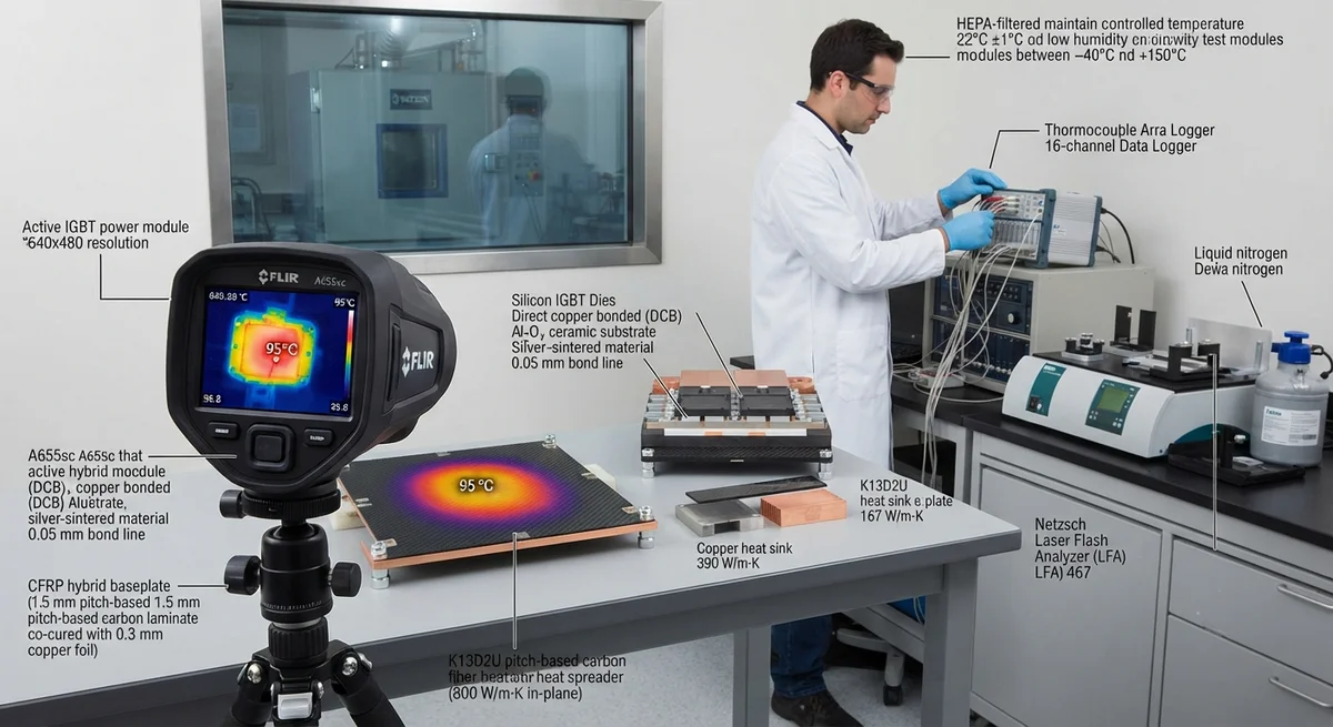
Engineering analysis of carbon fiber composites for thermal management in power electronics — comparing in-plane thermal conductivity, heat spreading performance, and weight savings vs aluminum and copper for IGBT modules, EV inverters, and LED systems.
Introduction: The Thermal Challenge in Modern Power Electronics
Power electronic systems — IGBT modules in traction inverters, SiC MOSFETs in EV charging infrastructure, GaN power amplifiers in RF systems, and high-brightness LED arrays — generate heat fluxes of 100–500 W/cm² at the chip level, with junction temperatures reaching 125–200°C. Effective thermal management is critical: every 10°C increase above the recommended junction temperature reduces semiconductor lifetime by approximately 50%. Traditional thermal management solutions rely on copper (thermal conductivity k = 390 W/m·K) or aluminum (k = 167–237 W/m·K) heat spreaders and heat sinks. However, these materials add significant weight — 30–60% of a typical IGBT module's total weight is the copper baseplate, and aluminum heat sinks for 10 kW inverters weigh 0.8–1.5 kg.
Carbon fiber composites, particularly those based on high-thermal-conductivity pitch-based fibers, offer a compelling alternative with in-plane thermal conductivities of 400–800 W/m·K — exceeding copper at 20–40% of the density. Combined with their low coefficient of thermal expansion (CTE of −1 to 0 ppm/°C for the fiber direction), tailorable anisotropy, and corrosion resistance, carbon fiber heat spreaders and heat sinks are increasingly adopted in aerospace power electronics, electric vehicle inverters, and high-power LED lighting. The global thermal management market for power electronics was valued at USD 7.8 billion in 2025, with composite-based solutions growing at 14–18% CAGR.
Thermal Conductivity Comparison: Materials for Heat Spreading
| Material | In-Plane Thermal Conductivity (W/m·K) | Through-Thickness Thermal Conductivity (W/m·K) | Density (g/cm³) | CTE (ppm/°C) | Specific Conductivity (W·m²/kg·K) |
|---|---|---|---|---|---|
| Copper (OFHC) | 390 | 390 | 8.96 | 16.5 | 43.5 |
| Aluminum 6061-T6 | 167 | 167 | 2.70 | 23.5 | 61.9 |
| Pitch-based CF (K13D2U, 800°C treatment) | 800 | 3–8 | 2.20 | −0.5 (fiber direction) | 363.6 |
| Pitch-based CF (YS-90A) | 540 | 3–6 | 2.15 | −0.2 | 251.2 |
| PAN-based CF (K1100) | 380 | 4–10 | 2.18 | 0.1 | 174.3 |
| CFRP with Cu mesh hybrid | 500–650 | 50–120 | 3.5–4.0 | 2–5 | 142.9–185.7 |
| Aluminum-graphite composite (50 vol%) | 320–480 | 300–450 | 2.8–3.2 | 6–12 | 114.3–171.4 |
| Copper-diamond composite (55 vol%) | 600–750 | 600–750 | 5.5–6.0 | 4–7 | 109.1–136.4 |
Pitch-based carbon fiber composites exhibit the highest specific thermal conductivity of any engineering material — K13D2U fiber composites achieve 363 (W·m²)/(kg·K), over 8× higher than copper. However, their thermal conductivity is highly anisotropic: the through-thickness conductivity (3–8 W/m·K) is two orders of magnitude lower than the in-plane value. This anisotropy must be carefully managed by using thin laminates (0.5–2.0 mm) oriented so that the fiber direction aligns with the heat spreading path, combined with a metal or graphite interface layer for through-thickness heat transfer into attached heat sinks.
Key Design Parameters for CFRP Heat Spreaders
- Fiber orientation optimization: Heat spreading efficiency is maximized when 70–80% of fibers are oriented in the primary heat flow direction (typically the x-axis along the baseplate). A quasi-isotropic layup [0/±45/90]ₛ reduces in-plane conductivity by 50–60% compared to unidirectional (UD) layup — from 800 W/m·K to approximately 320–400 W/m·K. For IGBT baseplate applications, a [0₆/90₂/0₆] layup is common, providing 85% of UD conductivity in the primary axis with sufficient transverse heat spreading.
- Thermal interface resistance: The bond line between the carbon fiber heat spreader and the ceramic substrate (Al₂O₃, AlN, or Si₃N₄) or the heat sink is the dominant thermal bottleneck. Without optimization, the thermal interface resistance can exceed 20 mm²·K/W — accounting for 30–50% of the total thermal budget. Solutions include co-curing a copper foil (0.1–0.3 mm) directly into the CFRP layup, or using a silver-sintered thermal interface (0.05 mm bond line, 5–10 mm²·K/W interface resistance).
- CTE matching: Power electronic substrates require CTE matching to prevent solder joint fatigue. Silicon has CTE = 2.6 ppm/°C, silicon carbide CTE = 4.0 ppm/°C, and Al₂O₃ ceramic CTE = 7.0 ppm/°C. Carbon fiber composites in the fiber direction have CTE = −0.5 to 0 ppm/°C, which can be tailored by adding a copper layer (CTE = 16.5 ppm/°C). A hybrid baseplate of 1.5 mm CFRP (fiber direction) co-cured with 0.5 mm copper achieves an effective CTE of 6.8 ppm/°C — closely matching Al₂O₃ ceramic substrates.
- Weight savings impact: Replacing a 3 mm copper IGBT baseplate (26.9 g/cm² of footprint area) with a 1.5 mm CFRP + 0.3 mm copper hybrid (3.2 g/cm²) reduces weight by 88%. For a 100 kW traction inverter, this saves 1.2–1.8 kg — representing a 12–18% weight reduction of the entire inverter unit. Weight savings of 1 kg in an EV are worth approximately $200–$300 in battery capacity or range extension.
- Through-thickness conductivity enhancement: Various methods exist to improve the poor through-thickness thermal conductivity of CFRP: (a) z-pinning with copper wires (0.5–1.0 mm diameter, 2–5% area fraction) achieves 40–80 W/m·K through-thickness at the cost of 10–15% in-plane conductivity reduction; (b) carbon nanotube (CNT) forest growth on fiber surfaces increases through-thickness conductivity to 15–30 W/m·K; (c) graphite interlayers (0.1 mm pyrolytic graphite sheet) between carbon fiber plies achieve 50–100 W/m·K through-thickness.
- Electrical insulation requirement: Carbon fiber is electrically conductive (resistivity 10⁻⁵–10⁻⁴ Ω·cm), requiring an insulating layer between the CFRP and any live electrical components. A 0.1 mm polyimide film (Kapton) or 0.15 mm thermally conductive ceramic-filled epoxy (0.5–1.0 W/m·K) provides sufficient electrical isolation (dielectric strength >5 kV/mm) while adding only 2–5°C to the thermal resistance.
Thermal Performance: IGBT Module Baseplate Case Study
| Parameter | Copper Baseplate (3 mm) | Aluminum-SiC (AlSiC) Baseplate (3 mm) | CFRP Hybrid Baseplate (1.5 mm CFRP + 0.3 mm Cu) | Unit |
|---|---|---|---|---|
| Thermal resistance, junction-to-baseplate (R₍th,j−₎b) | 0.12 | 0.14 | 0.13 | K/W |
| Thermal resistance, baseplate-to-heatsink | 0.03 | 0.03 | 0.04 | K/W |
| Total thermal resistance junction-to-heatsink | 0.15 | 0.17 | 0.17 | K/W |
| Baseplate weight (100 × 140 mm module) | 376 | 168 | 45 | g |
| CTE (in-plane) | 16.5 | 8.0 | 6.8 | ppm/°C |
| Thermal cycling lifetime (power cycling, ΔT=80°C) | 30,000 | 60,000 | 75,000 | cycles |
| Weight reduction vs copper | — | 55% | 88% | |
| Material cost (per module) | $4–$8 | $12–$20 | $25–$45 | USD |
The CFRP hybrid baseplate (1.5 mm pitch-based CFRP co-cured with 0.3 mm copper) achieves near-equivalent thermal resistance to a 3 mm copper baseplate while providing 88% weight reduction, better CTE matching to ceramic substrates, and 2.5× longer thermal cycling lifetime. The cost premium — approximately $25–$45 vs $4–$8 for copper — is justified in aerospace and high-performance EV applications where every kilogram of weight saving enables extended range, higher payload, or reduced battery capacity.
Manufacturing Considerations for CFRP Thermal Management Components
- Prepreg selection: Pitch-based carbon fiber prepregs (e.g., K13D2U or YS-90A) are supplied in unidirectional tape form with epoxy or cyanate ester resin systems. The resin content must be tightly controlled (30–35% by weight) because excess resin dramatically reduces in-plane conductivity. A 5% increase in resin content from 30% to 35% reduces in-plane thermal conductivity by 12–18%.
- Consolidation method: Autoclave consolidation (6–8 bar, 180°C, 2-hour hold) achieves the highest fiber volume fraction (60–65%) and lowest void content (<0.5%), maximizing thermal conductivity. Vacuum-bag-only (VBO) processing achieves 55–60% FVF and is suitable for prototypes or low-volume production. Compression molding (50–100 bar, 150°C, 15–30 min cycle) is preferred for high-volume production >10,000 units/year.
- Copper integration: Co-curing copper foil (0.1–0.5 mm, rolled annealed grade) into the CFRP layup requires surface treatment of the copper: micro-etching (Cutz-SB or equivalent) followed by silane coupling agent application. Peel strength of the copper-CFRP bond after co-curing should exceed 8 N/mm for reliable thermal cycling performance.
- Quality control: Thermal conductivity of each production batch should be verified by laser flash analysis (ASTM E1461) on test coupons from the same cure cycle. Acceptance criteria: in-plane conductivity within ±10% of target, void content <1.0%, and fiber volume fraction within ±2% of specification.
Frequently Asked Questions
Can carbon fiber heat spreaders directly replace copper baseplates in existing IGBT module designs?
Yes, but with two modifications. First, the mounting interface must accommodate the thinner CFRP+Cu hybrid (1.5–2.0 mm vs 3.0 mm for copper). This requires either a redesigned module housing to maintain proper standoff height, or a thicker thermal interface material (TIM) layer to fill the gap — which increases thermal resistance by 5–10%. Second, the electrical isolation layer must be verified: CFRP is electrically conductive, so a polyimide or ceramic-filled epoxy insulation layer must be present between the CFRP baseplate and the DCB (direct copper bonded) substrate. Most existing copper baseplate designs already include an Al₂O₃ or AlN ceramic substrate bonded to the baseplate, but the bond line must be re-validated for the CFRP surface energy and CTE.
What is the maximum operating temperature for CFRP thermal management components?
For standard epoxy-based CFRP, the continuous operating temperature is 150–180°C (glass transition temperature T_g of the fully cured epoxy). Above T_g, the resin softens, causing a 40–60% reduction in through-thickness thermal conductivity and potential creep under clamping pressure. For higher-temperature applications (180–250°C), cyanate ester or bismaleimide (BMI) resin systems are used, with T_g values of 250–320°C. The fiber itself (pitch-based carbon) is thermally stable to 3,000°C in inert atmosphere, so the resin system is the limiting factor. For SiC and GaN power devices with junction temperatures up to 200–250°C, BMI-based pitch-fiber CFRP is recommended.
How does the cost of CFRP thermal solutions compare to conventional materials at production scale?
At production volumes of 1,000–10,000 units/year, a CFRP hybrid baseplate (1.5 mm CFRP + 0.3 mm Cu) costs $25–$45 per module, compared to $4–$8 for copper and $12–$20 for AlSiC. The cost premium is 3–10× over copper. However, the system-level value of weight savings is significant: in aerospace power electronics, saving 1 kg is worth $1,000–$10,000 depending on the platform. In automotive, saving 1 kg in the inverter enables approximately 0.5 kWh less battery capacity (worth $50–$75 at pack level) or 2–3 km additional range. At volumes above 50,000 units/year, compression-molded CFRP heat spreaders are projected to reach $15–$25 per module, approaching AlSiC cost parity while offering 60% lower density.
What is the thermal conductivity degradation of CFRP under thermal cycling conditions?
CFRP thermal management components typically show 3–8% reduction in in-plane thermal conductivity after 1,000 thermal cycles (−40°C to +150°C, 30-minute dwell). The degradation mechanism is microcracking of the epoxy matrix at the fiber-matrix interface, which increases the thermal contact resistance between fibers. The rate of degradation stabilizes after 500–1,000 cycles. For aerospace applications requiring 10,000+ thermal cycles (typical of LEO satellite thermal management), toughened epoxy systems or cyanate ester resins reduce degradation to <3% after 2,000 cycles. By comparison, copper baseplates show no thermal conductivity degradation but accumulate solder fatigue damage that eventually causes module failure at 20,000–40,000 cycles depending on the ΔT.
Can carbon fiber be used for both heat spreading and structural support simultaneously?
Yes — this dual-function capability is one of the key advantages of CFRP thermal management. In aerospace power electronic units, the CFRP baseplate serves as both the thermal heat spreader and the primary structural mounting plate, eliminating the need for a separate chassis or support frame. The structural requirements — typically flexural modulus >100 GPa and ultimate bending strength >500 MPa — are readily satisfied by a quasi-isotropic [0/±45/90]ₛ laminate with 55–60% FVF. The thermal and structural requirements must be balanced: a unidirectional layup maximizes heat spreading but provides insufficient off-axis structural stiffness. The optimal design typically uses a [0₆/±45/90]ₛ layup where the 0° plies (70–75% of the laminate) provide high in-plane thermal conductivity in the primary direction, and the ±45/90 plies provide torsional and transverse structural rigidity.
Conclusion
Carbon fiber composites, particularly pitch-based fiber systems with in-plane thermal conductivities exceeding copper at 20–40% of the density, represent a transformative material solution for thermal management in power electronics. The combination of high specific thermal conductivity, tailorable CTE matching to ceramic substrates, corrosion resistance, and dual-function structural-thermal capability creates compelling value in aerospace power electronics, EV traction inverters, and high-power LED lighting systems. The key design considerations for B2B buyers include: fiber selection (pitch-based K13D2U or YS-90A for maximum conductivity; PAN-based K1100 for balanced cost-performance), resin system selection (epoxy for 150–180°C, BMI for 200–250°C), copper integration method (co-cured foil for hybrid baseplates), and through-thickness conductivity enhancement strategy (z-pinning, CNT forests, or graphite interlayers). While the upfront material cost premium over copper remains significant at 3–10× per module, the system-level benefits — weight savings of up to 88%, extended thermal cycling lifetime by 2.5×, and potential structural integration — justify adoption in weight-sensitive and high-reliability power electronic applications.
Part of topic
Related Articles
- Carbon Fiber Mooring for Floating Offshore Wind: Fatigue and Corrosion in Deep Water
- Carbon Fiber Bicycle Frame Optimization: Layup Design and Manufacturing for Competitive Racing
- Carbon Fiber CFRP Retrofit for Infrastructure: Bridge and Building Seismic Strengthening
- Carbon Fiber Medical Imaging Equipment: Lightweight Gantry and Couch Structures for MRI/CT
- Carbon Fiber EV Battery Enclosures: Crash Safety and Electromagnetic Shielding Design
- Carbon Fiber Structures for Low-Altitude Economy: UAV Airframes and eVTOL Components
Interested in Our Products?
Contact our team for competitive pricing and technical specifications.
Get a QuoteRelated Products

Carbon fiber standard plate-3k stripe
Lightweight, ultra-rigid standard sheets for drone fuselages, robot housings, facades and structural applications.

Carbon Fiber Plate — 3K Twill T700 1.5mm
Thin 1.5mm carbon fiber plate with 3K twill weave surface. Lightweight and stiff, commonly used for covers, panels, drone bodies, and applications requiring a premium aesthetic appearance.

Square Carbon Fiber Tube — 3K Twill T700
Square cross-section carbon fiber tube manufactured with 3K twill weave for torsional strength. Preferred for structural frames, trusses, and support columns where rectangular geometry offers design flexibility.

Carbon Fiber Plate — 3K Twill T700 3.0mm
Medium-thickness 3.0mm carbon fiber plate offering significantly higher load capacity while maintaining attractive 3K twill finish. Suitable for structural brackets, reinforcement plates, and load-bearing panels.

Carbon Fiber Plate — UD Unidirectional T700
Unidirectional carbon fiber plate with all fibers oriented in a single direction for maximum strength along the fiber axis. Essential for structural reinforcements, splints, and applications where load direction is predictable.