
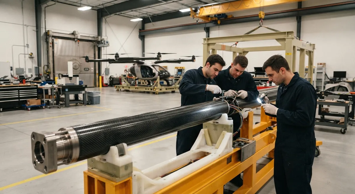
Every eVTOL aircraft is a trade of grams against range. Motors, batteries, and structure compete for the same takeoff weight, so a kilogram saved becomes a kilogram of battery. The carbon fiber eVTOL boom arm is one of the best places to find that saving: it sits at the far end of the a
Introduction
Every eVTOL aircraft is a trade of grams against range. Motors, batteries, and structure compete for the same takeoff weight, so a kilogram saved becomes a kilogram of battery. The carbon fiber eVTOL boom arm is one of the best places to find that saving: it sits at the far end of the aircraft, where mass carries the heaviest penalty and loads are punishing.
Booms connect the fuselage to the motors. They carry thrust, absorb rotor vibration, transmit crash loads, and must survive bird strike and ground handling. This article covers boom load cases, crash energy absorption, motor mount integration, and the weight-for-battery tradeoff.
What a Boom Arm Carries on an eVTOL
An eVTOL boom is a slender tube, typically 2.5-5 m long on a four-seat lift+cruise aircraft, that keeps rotors clear of the fuselage and each other, improving control authority and allowing larger, quieter propellers. Boom mass on a 2,000-3,000 kg eVTOL commonly runs 15-40 kg per side.
The major eVTOL configurations place different demands on the boom:
- Multirotor: fixed rotors only; booms are short and stiff, sized for vertical thrust and vortex ring loads.
- Lift+cruise: separate lift rotors on the booms and a cruise propeller on the tail; booms carry mostly vertical lift plus forward loads during transition.
- Vectored thrust: tilt rotors pivot through 90 degrees, adding articulation loads, actuator weight, and wiring and cooling runs inside the boom.
In every configuration the boom is a load path, a housing for wiring and cooling, and a crash structure.
Load Cases That Drive Boom Design
Boom sizing starts from discrete load cases, each with its own limit load and safety factor. Motor thrust dominates in normal flight, but fatigue, crash, and discrete events often set the design.
Representative loads for a four-seat lift+cruise eVTOL:
| Load case | Typical value | Design impact |
|---|---|---|
| Motor thrust per unit, continuous | 2-4 kN | Sets static sizing and joint loads |
| Motor thrust per unit, burst | 5-9 kN | Drives ultimate strength of the mount |
| Rotor vibration at blade pass frequency | 20-100 Hz | Drives fatigue life and damping |
| Landing and ground handling | 2.0-3.0 g at boom tip | Adds bending and torsion cases |
| Crash energy per boom, vertical descent | 10-25 kJ | Sets crush zone energy capacity |
| Bird strike equivalent energy | 300-800 J | Drives leading edge and skin tolerance |
Vibration is the hidden cost: a spinning rotor produces a strong harmonic at blade pass frequency that a stiff composite boom transmits into the fuselage unless tuned or isolated. Crash offers the most design freedom, because carbon fiber outperforms metal here.
Crash Energy Absorption: Progressive Failure Instead of Snap
A composite tube does not bend and snap like an aluminum beam. Designed well, it fails progressively at a crush front where the tube wall splays into fronds, consuming energy through fiber fracture, delamination, and friction over a long stroke.
Specific energy absorption (SEA) is the energy absorbed per unit mass crushed:
| Material and design | SEA (kJ/kg) | Failure mode |
|---|---|---|
| Aluminum tubes | 20-30 | Bending, buckling, tearing |
| CFRP tubes, poorly designed | 20-40 | Premature splitting and snap-through |
| CFRP tubes, crush-initiated and splayed | 50-90 | Stable progressive crushing |
Two to three times the energy per kilogram of metal means a lighter boom can absorb the same crash energy. That requires a crush initiator at the tube end, a layup that splays rather than splits, and a structure that keeps the stroke controlled. The vertical descent case, protecting occupants from high sink rates, is where this pays off.
Motor Mount Integration and Load Introduction
A boom tube is only as strong as the joint that ties the motor to it. Bolting directly into composite risks crushing the laminate locally, so mounts use metallic inserts and co-cured fittings to spread load into the wall.
- Metallic inserts: titanium or stainless steel bushings receive the motor bolts and spread bearing load into the laminate.
- Co-cured fittings: titanium fittings cured together with the tube form a continuous load path with no secondary bonding step.
- Load introduction straps: extra fiber carries concentrated mount loads back into the tube walls.
- Insulated interfaces: isolating inserts from the carbon prevents galvanic corrosion.
Inserts are typically co-cured into the structure rather than bonded afterward, then validated by pull-out and bearing tests before certification.
Manufacturing Routes for Boom Tubes
Boom geometry suits three established processes, chosen for volume, cost, and quality:
- Prepreg autoclave: the highest quality and design flexibility, used for low-volume certification hardware.
- Resin transfer molding (RTM): net-shape tubes with good surface finish, suited to mid-volume production.
- Filament winding: the fastest route for straight and tapered tubes, with hoop strength that suits pressure and bending loads.
At hundreds of units a year, the boom is usually a compromise: filament-wound or RTM tubes for the straight sections, with co-cured metallic end fittings at the motor mounts.
Weight Budget, Batteries, and Range
In electric aircraft the relationship is direct. For a fixed takeoff weight, 1 kg of structure saved allows roughly 1 kg more battery, and a few percent of battery mass is worth real kilometers. A boom family saving 5-10 kg on a four-seat aircraft is mission payload or range.
Weigh every decision, from SEA to insert selection, against this equation: a kilogram of crash structure and a kilogram of battery are the same currency.
Damage Tolerance, Inspection, and Certification Context
Boom tubes see handling damage, tool drops, and ground strikes, and must still carry load with that damage present. Designers assume barely visible impact damage (BVID) and set strain allowables low enough that the tube survives without losing residual strength. Ultrasonic testing finds delamination, thermography scans large areas, and borescopes check the interior.
On certification, eVTOL programs follow EASA SC-VTOL and FAA Part 23 and Part 21 pathways, which require crashworthy structural design, occupied cabin protection, and integrity shown by analysis and test. Requirements evolve, so OEMs should confirm current rules with their authorities.
Frequently Asked Questions
Why is carbon fiber better than aluminum for eVTOL boom arms?
Carbon fiber boom arms can absorb 50-90 kJ/kg of crash energy through progressive crushing, versus 20-30 kJ/kg for aluminum, at roughly half the density. The same energy absorption is achieved with less mass, and that saving converts directly into battery weight and range.
How is crash energy absorbed in a carbon fiber boom?
Through controlled progressive crushing. A crush initiator at the tube end starts a stable failure front where the tube wall splays into fronds, consuming energy through fiber fracture, delamination, and friction over a long stroke, instead of the sudden snap of a metal beam.
How are electric motors attached to a carbon fiber boom?
Motors are attached through metallic inserts and co-cured fittings. Titanium or stainless steel inserts spread bearing loads into the laminate, load introduction straps carry concentrated mount forces back into the tube walls, and insulated interfaces prevent galvanic corrosion.
Conclusion
The carbon fiber eVTOL boom arm is a small part with an outsized job. It carries the motors, survives the crash, and every kilogram it saves becomes battery and range. Progressive crushing gives CFRP two to three times the energy absorption of metal per kilogram, co-cured inserts solve load introduction, and the weight-for-battery trade makes it worthwhile.
YongXian supplies aerospace-grade carbon fiber materials for boom arms and load-bearing tubes. Explore our carbon fiber product range or contact our engineering team to discuss laminate design, inserts, and manufacturing support for your program.
Part of topic
Related Articles
- Carbon Fiber Mooring for Floating Offshore Wind: Fatigue and Corrosion in Deep Water
- Carbon Fiber Bicycle Frame Optimization: Layup Design and Manufacturing for Competitive Racing
- Carbon Fiber CFRP Retrofit for Infrastructure: Bridge and Building Seismic Strengthening
- Carbon Fiber Medical Imaging Equipment: Lightweight Gantry and Couch Structures for MRI/CT
- Carbon Fiber EV Battery Enclosures: Crash Safety and Electromagnetic Shielding Design
- Carbon Fiber Structures for Low-Altitude Economy: UAV Airframes and eVTOL Components
Interested in Our Products?
Contact our team for competitive pricing and technical specifications.
Get a QuoteRelated Products

Carbon fiber standard plate-3k stripe
Lightweight, ultra-rigid standard sheets for drone fuselages, robot housings, facades and structural applications.

Carbon Fiber Plate — 3K Twill T700 3.0mm
Medium-thickness 3.0mm carbon fiber plate offering significantly higher load capacity while maintaining attractive 3K twill finish. Suitable for structural brackets, reinforcement plates, and load-bearing panels.

Carbon Fiber Plate — 3K Twill T700 1.5mm
Thin 1.5mm carbon fiber plate with 3K twill weave surface. Lightweight and stiff, commonly used for covers, panels, drone bodies, and applications requiring a premium aesthetic appearance.

Square Carbon Fiber Tube — 3K Twill T700
Square cross-section carbon fiber tube manufactured with 3K twill weave for torsional strength. Preferred for structural frames, trusses, and support columns where rectangular geometry offers design flexibility.

Carbon Fiber Plate — UD Unidirectional T700
Unidirectional carbon fiber plate with all fibers oriented in a single direction for maximum strength along the fiber axis. Essential for structural reinforcements, splints, and applications where load direction is predictable.