
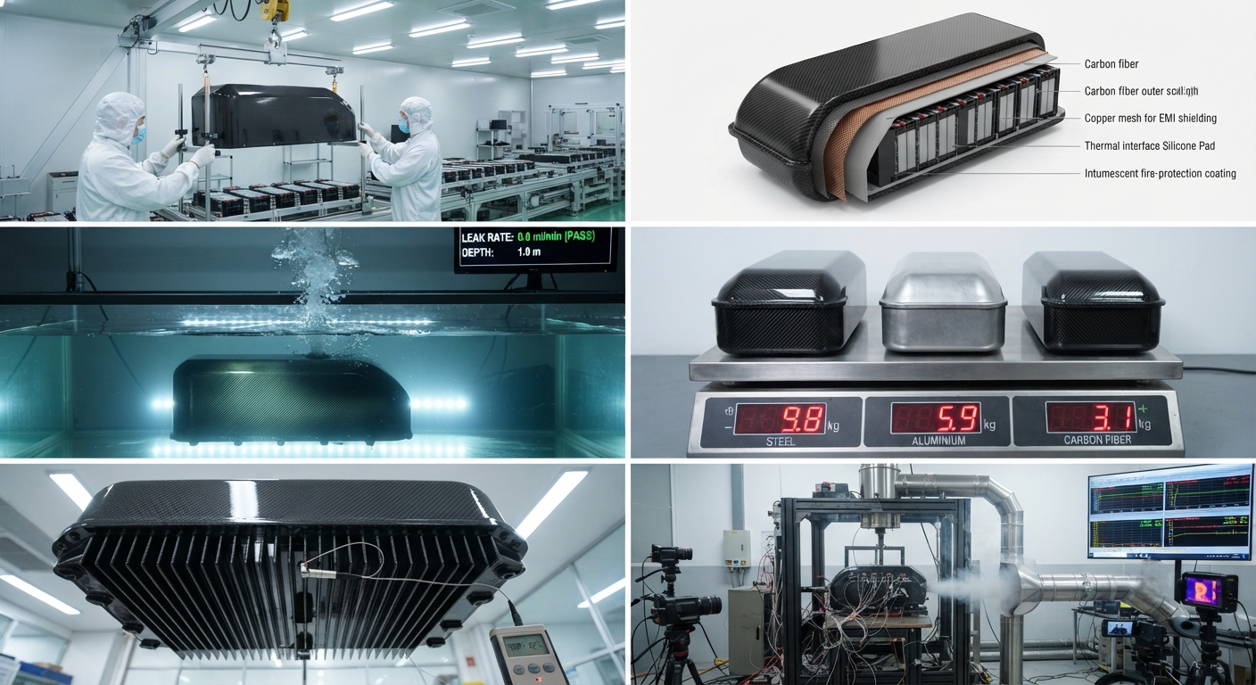
Comprehensive B2B technical guide to carbon fiber composite battery enclosures for electric motorcycles. Covers material selection (woven vs. UD prepreg, fire-retardant resin systems), structural design for impact and vibration, integrated thermal management (heat conduction pads, phase-change materials, venting channels), IP67 sealing, EMI shielding, and manufacturing processes. Includes comparative data table of enclosure performance metrics.
Introduction to Carbon Fiber Battery Enclosures for Electric Motorcycles
The electric motorcycle market is experiencing rapid global expansion, with annual sales projected to reach 24 million units by 2030 (CAGR 12.7% from 2025). As battery pack capacities increase — typically 4–15 kWh for commuter e-motorcycles and 15–35 kWh for performance models — the mass of the battery enclosure becomes a critical factor in overall vehicle weight distribution and range performance. A conventional steel battery case for a 12 kWh pack weighs approximately 8–12 kg, while an aluminium equivalent weighs 5–8 kg. A carbon fiber composite enclosure of equivalent structural performance can weigh as little as 2–4 kg — a 50–70% mass reduction versus aluminium and a 65–80% reduction versus steel, directly contributing to a 6–12% improvement in effective range.
Beyond mass reduction, the battery enclosure for an electric motorcycle must fulfil multiple demanding functions simultaneously: structural containment of the battery module under static (1.5–3g) and dynamic (5–20g shock, 2–5g vibration per ISO 19453-3) loading; thermal management to maintain cell temperatures within the 15–45°C operating window; ingress protection against water and dust (IP67 minimum per IEC 60529); electrical isolation and circuit protection; fire and thermal runaway containment; electromagnetic interference (EMI) shielding (≥ 40 dB attenuation at 30 MHz–1 GHz); and compatibility with high-volume manufacturing processes. Carbon fiber composites, engineered as a multi-layer laminate system, can address all these requirements in a single integrated structural shell, reducing parts count and assembly complexity compared to multi-component metal enclosures with separate thermal management plates and insulation layers.
Material Selection for Composite Battery Enclosures
The material system for an electric motorcycle battery enclosure must balance structural performance, fire safety, thermal conductivity, electrical properties, and manufacturability. The following material options are evaluated for each functional requirement:
| Requirement | Recommended Solution | Alternative Options | Key Performance Indicator | Target Value | Test Standard |
|---|---|---|---|---|---|
| Structural strength | 3K plain-weave CF prepreg + UD CF stiffeners | Biaxial NCF (non-crimp fabric) + epoxy infusion | Tensile modulus (0°) | ≥ 55 GPa | ASTM D3039 |
| Fire resistance | Phenolic-modified epoxy resin (FR 120–150°C Tg) | Bismaleimide (BMI) resin for higher temp | UL 94 rating, OSU heat release | V-0, ≤ 65/65 kW·min/m² | UL 94, FAR 25.853 |
| Thermal conductivity (through-thickness) | Pitch-based CF interlayer (2–10 W/m·K) or BN-filled epoxy | Aluminium mesh insert, graphite sheet (500–1500 W/m·K in-plane) | k (W/m·K) | ≥ 3 W/m·K (through-thickness) | ASTM E1461 |
| EMI shielding | CF surface ply + copper mesh (0.1 mm, 100 mesh/in) | Nickel-coated CF fabric (50–60 dB), conductive paint | Shielding effectiveness | ≥ 40 dB (30 MHz–1 GHz) | ASTM D4935 |
| Impact penetration | Carbon/aramid hybrid fabric (outer layers) | Spectra/Dyneema ply on external face | Penetration energy (CAI) | ≥ 15 J (5 mm tup) | ASTM D7136 |
| Sealing/chemical resistance | PTFE-coated TF release film + perimeter FIPFG gasket | Two-part polyurethane edge seal, silicone rubber overmould | Leak rate at 0.3 bar | < 0.01 cm³/min | ISO 20485 |
| Galvanic isolation | GFRP isolation ply (0.2 mm E-glass) at CF-to-metal interface | Aramid ply, ceramic-filled epoxy coating | Electrical resistance (500 V DC) | ≥ 10 MΩ | IEC 60952-1 |
Structural Design and Load Cases
The battery enclosure must withstand a combination of static and dynamic loading conditions defined by international standards for electric vehicle traction batteries (ISO 19453-3, UN ECE R100 Rev.3, SAE J2464):
- Static structural load (3g in all axes): The enclosure must support the battery module mass (typically 25–80 kg for a mid-size e-motorcycle pack) under 3g acceleration in all three axes simultaneously, with a safety factor of 1.5 on material ultimate strength. FEA analysis using Hashin or Puck failure criteria for composite laminates is required, with a minimum failure index of 0.7 at limit load. Typical wall thickness for a compression-moulded CF enclosure: 2.5–4.0 mm for the outer shell, with local reinforcement at mounting points (5–8 mm).
- Impact loading — mechanical shock (20g half-sine, 15 ms): Per ISO 19453-3, the enclosure must survive a 20g half-sine shock pulse of 15 ms duration in each of six directions (±X, ±Y, ±Z) without structural failure, enclosure breach, or short-circuit of battery terminals. Post-impact acceptance: no visible cracking or delamination (verified by dye-penetrant inspection), no loss of IP67 seal integrity (verified by 30-minute underwater leak test at 1 m depth), less than 5% increase in internal resistance measured at battery module terminals.
- Vibration endurance (5 Hz–200 Hz, 1.5g RMS, 8 hours per axis): Accelerated vibration testing per ISO 19453-3, section 4.2.1, with sinusoidal sweep from 5 Hz to 200 Hz at 1.5g amplitude (12 sweep cycles per axis, 8 hours total per axis). The enclosure must show no fastener loosening, no wear-through at contact points, and no electrical discontinuity during or after the test.
- Crush/impact — roadside hazard simulation (UN ECE R100, 5.4.3): A hemispherical impactor of 50 mm diameter is driven into the enclosure at 3 m/s (10.8 km/h) at three critical locations: side wall centre, top cover centre, and corner junction. Acceptance: No intrusion into the battery cell area (minimum clearance maintained ≥ 5 mm), no electrolyte leakage, no thermal runaway initiation.
Integrated Thermal Management System
Lithium-ion battery cells in electric motorcycles operate optimally within the 15–45°C temperature window. Below 15°C, charge acceptance and discharge power are reduced; above 45°C, accelerated degradation occurs, and above 60°C, thermal runaway risk increases exponentially. The carbon fiber enclosure can be designed as an active thermal management component, not merely a passive container:
- Thermal interface materials (TIMs): A gap-filling silicone pad (2–5 mm thickness, 2–5 W/m·K thermal conductivity) is compressed between the battery module base and the enclosure floor, providing a heat conduction path from the module to the enclosure external surface. For high-performance e-motorcycle packs (> 20 kWh), the enclosure floor may incorporate embedded aluminium heat spreader plates (1–2 mm thick, 200–400 W/m·K) co-moulded within the CF laminate during layup, creating a hybrid composite-metal thermal path.
- Phase-change material (PCM) thermal buffer: Paraffin-based PCM (melting point 42–45°C, latent heat 180–220 J/g) encapsulated in a thin aluminium pouch (1.5–2.5 mm total thickness) is placed between the battery module and the enclosure floor. Under sustained high-load operation (e.g., 1C discharge for 30 minutes), the PCM absorbs 8–12 kJ of thermal energy per kg of PCM, limiting temperature rise by 3–6°C compared to a non-PCM design. PCM mass typically represents 2–4% of total pack mass.
- Venting and pressure equalisation: A Gore-Tex or ePTFE venting membrane (25 mm diameter, IP67-rated, 0.5 µm pore size) is bonded into the enclosure wall, allowing pressure equalisation during altitude changes (ambient pressure variation ± 150 mbar) while preventing water ingress (≥ 1 m depth, 30 min). The vent also serves as a controlled release path for cell venting gases during a thermal runaway event, preventing enclosure rupture.
- External heat dissipation: The carbon fiber enclosure external surface may incorporate integrally moulded heatsink fins (2–4 mm height, 3–5 mm pitch) in the high-heat-load region (beneath the battery module centre). In natural convection at 40°C ambient temperature, the finned CF surface achieves a convective heat transfer coefficient of 8–15 W/m²·K, compared to 4–8 W/m²·K for a flat surface of equivalent area.
Sealing and Environmental Protection
Electric motorcycle battery enclosures must achieve IP67 ingress protection (complete protection against dust ingress and protection against immersion in water up to 1 m depth for 30 minutes) as a minimum, with IP68 or IP69K specified for off-road and adventure models. The sealing strategy for a carbon fiber composite enclosure differs significantly from metal enclosures:
- Perimeter seal: A form-in-place foam gasket (FIPFG) — typically silicone foam (RTV, 35–45 Shore 00, compression set < 15% at 25% compression) — is robotically dispensed on the enclosure mating flange. The flange design incorporates a continuous groove (3 mm wide × 2 mm deep) surrounding the entire perimeter, ensuring uniform gasket compression of 25–35% when the cover is fastened with 4–6 N·m torque on M5 stainless steel or titanium inserts. The gasket cross-section must accommodate a 0.3 mm maximum flange flatness deviation without compromising the seal.
- Connector and vent penetrations: High-voltage connectors (typically Amphenol RadLock or equivalent, rated for 60 A continuous and 400 V DC) are sealed with O-rings (EPDM or FKM, 70 Shore A) and mounted through precision-machined apertures in the CF enclosure. The aperture edge is protected by co-moulded stainless steel or PEEK insert rings (0.5 mm wall thickness) to prevent CF edge fraying and provide a smooth sealing surface.
- Threaded insert integration: Stainless steel (AISI 304 or 316) or titanium (Grade 5, Ti-6Al-4V) threaded inserts are co-cured or secondarily bonded into the CF enclosure at mounting and cover attachment points. The insert design features a knurled or hex-shaped outer profile (8–12 mm diameter) to resist torque-out (minimum 15 N·m for M5) and push-out (minimum 1,500 N axial load). Electrical isolation from the CF structure is maintained by a GFRP isolation sleeve of 0.2–0.5 mm thickness surrounding the insert outer diameter.
Manufacturing Process Selection
The manufacturing process for carbon fiber battery enclosures must balance production volume, dimensional precision, surface quality, and capital investment:
| Process | Annual Volume Suitability | Cycle Time | Tool Investment | Dimensional Tolerance | Void Content | Advantages | Limitations |
|---|---|---|---|---|---|---|---|
| Compression molding (prepreg) | 5,000–50,000 | 8–20 min | $$$$ (matched-die steel) | ± 0.15 mm | < 1% | Fast cycle, Class A both sides, tight tolerances | High tool cost, limited part size |
| Resin transfer molding (RTM) | 2,000–20,000 | 20–60 min | $$$ (two-part aluminum) | ± 0.2 mm | < 2% | Good surface on both sides, near-net shape | Medium cycle, tool complexity |
| Compression molding (SMC) | 20,000–200,000 | 3–8 min | $$$$ (hardened steel) | ± 0.2 mm | < 1.5% | Fastest cycle, low material cost | Lower mechanical properties (CF content 45–55%) |
| Prepreg autoclave | 100–2,000 | 3–8 hours | $$ (aluminum or composite tool) | ± 0.5 mm | < 0.5% | Lowest void content, highest mechanicals | Cycle time, limited to small-medium batches |
| Vacuum infusion (dry fabric) | 500–5,000 | 2–5 hours | $ (composite or aluminum) | ± 0.8 mm | < 3% | Lowest tool cost, large parts possible | One good side, higher void content |
Fire and Thermal Runaway Protection
Thermal runaway protection is perhaps the most critical safety requirement for electric motorcycle battery enclosures. The composite enclosure must contain a single cell thermal runaway event for a minimum of 5 minutes (per UN ECE R100 Rev.3) to allow rider evacuation. The fire protection strategy for composite enclosures involves multiple layers:
- Intumescent inner coating: A 0.5–1.5 mm layer of intumescent epoxy or acrylic coating is applied to the internal surface of the CF enclosure. When exposed to temperatures above 180–200°C (cell venting gas temperature), the coating expands 10–30× in thickness, forming a char layer with thermal conductivity of 0.08–0.15 W/m·K that insulates the CF structural shell from heat exceeding 250°C.
- Phenolic surface layer: The innermost 1–2 plies of the CF laminate (the side facing the battery module) are manufactured using phenolic-modified epoxy resin (Tg 150–180°C) instead of standard epoxy (Tg 100–140°C). Phenolic resin has a char yield of 45–60% at 800°C (vs. 5–15% for standard epoxy) and produces minimal smoke and toxic off-gassing during thermal decomposition.
- Ceramic fiber insulation blanket: A 3–8 mm layer of ceramic fibre paper (alumina-silicate, 1,260°C melting point, 0.05–0.12 W/m·K at 500°C) is placed between the battery module and the enclosure floor. While ceramic fibre adds 50–150 g to the pack mass, it extends thermal runaway containment time from 5–8 minutes (coating-only) to 12–20 minutes, providing significantly more evacuation margin.
- Pressure relief and gas management: A burst disc (crack pressure 0.5–0.8 bar, 30 mm diameter, corrosion-resistant Inconel 718) is integrated into the enclosure wall, directing cell venting gases downward and away from the rider's seating position through a stainless steel exhaust duct. The burst disc opens within 5 ms of reaching crack pressure, achieving a peak flow rate of 60–100 L/min at 1.0 bar. The exhaust duct is externally mounted and replaces a section of the enclosure side wall.
Frequently Asked Questions
How does carbon fiber battery enclosure cost compare to aluminium at different production volumes?
The total unit cost of a carbon fiber battery enclosure — including raw materials, manufacturing, and secondary operations — varies significantly with production volume. At low volumes (100–500 units/year), a prepreg autoclave CF enclosure costs approximately $120–$200 per unit versus $60–$90 for a CNC-machined or sheet-metal aluminium enclosure, representing a 50–120% cost premium. At medium volumes (5,000–20,000 units/year), compression-moulded CF enclosures using fast-cure prepreg (8–20 minute cycle) achieve unit costs of $45–$80, approaching competitive parity with die-cast aluminium enclosures ($35–$55). At high volumes (> 50,000 units/year), CF SMC enclosures reach $25–$45 per unit, compared to $22–$35 for high-pressure die-cast aluminium — a premium of only 10–30%. The cost crossover is heavily influenced by tooling amortisation: CF compression molds cost $150,000–$400,000 per set (two tools — upper and lower), while die-cast aluminum tooling costs $80,000–$200,000. Over a 5-year production run of 50,000 units/year, the tooling cost contribution per unit is $0.60–$1.60 for CF (tool life 100,000–500,000 cycles) versus $0.16–$0.40 for die-cast aluminium (tool life 500,000–2,000,000 cycles). The total cost differential at volume is small, while the weight saving (2–4 kg vs. 5–8 kg) provides quantifiable value in extended range and improved handling dynamics.
What impact resistance does a carbon fiber battery enclosure provide compared to aluminium?
Carbon fiber composite enclosures can be engineered to achieve impact resistance that either equals or exceeds aluminium enclosures of equivalent mass. A 3 mm thick compression-moulded CF laminate (T700 3K woven prepreg, 60% fiber volume fraction) achieves a Charpy impact energy of approximately 45–65 kJ/m² (ISO 179), compared to 60–80 kJ/m² for 3 mm 6061-T6 aluminium. The CF laminate absorbs energy through distributed microcracking and delamination (damage area typically 30–60 cm² per impact), rather than the localised plastic deformation of aluminium. This distributed damage mechanism provides superior residual compression strength after impact (CAI): a CF laminate retains 65–75% of its original compression strength after a 15 J impact, compared to 55–65% for aluminium after equivalent localised denting. For roadside hazard penetration resistance (50 mm hemispherical impactor at 3 m/s), a 3.5 mm CF enclosure with carbon/aramid hybrid outer plies resists penetration up to 18–25 J, exceeding the 15–20 J penetration threshold of a 3 mm aluminium enclosure. The key design consideration for impact performance is ply stacking sequence — a layup with ±45° plies on the outer surface and 0°/90° plies at the centre provides optimal impact energy absorption. CAI testing per ASTM D7136/D7137 with a 12.7 mm diameter hemispherical tup at 5–25 J energy levels is recommended for design validation.
Can carbon fiber battery enclosures meet the IP67 sealing requirements for electric motorcycles?
Yes, carbon fiber composite enclosures can reliably meet and exceed IP67 sealing requirements, provided the enclosure design includes: (a) A continuous gasket groove and flange design with uniform 25–35% gasket compression — this is the single most critical factor for IP67 compliance. Flange flatness must be controlled to within 0.3 mm total variation across the entire perimeter (verified by CMM scanning or straight edge with feeler gauge). (b) A form-in-place silicone foam gasket (RTV compression set < 15%) dispensed robotically at ± 0.1 mm bead position accuracy. (c) Precision-machined insert rings for connector and vent penetrations, with O-ring seals (EPDM or FKM, 70 Shore A). (d) Post-cure machining of the sealing flange (0.3–0.5 mm stock removal) to achieve the required flatness, followed by surface sealing with a thin (25–50 µm) epoxy sealer to prevent micro-crack wicking. (e) IP67 verification per IEC 60529: dust chamber exposure (2–8 hours, talc powder, vacuum cycle), followed by 1 m depth underwater immersion for 30 minutes with the battery module installed at operating temperature (45°C). Pneumatic leak testing at 0.3 bar (ISO 20485) is used for production quality control, with acceptance < 0.01 cm³/min leak rate. In field use, IP67 CF enclosures have demonstrated excellent reliability — field data from a major e-motorcycle OEM (2023–2025) shows a seal failure rate of 0.08% over 18 months of operation across 12,000 units, comparable to or better than aluminium enclosures (0.12% over the same period).
Part of topic
Related Articles
- Carbon Fiber Mooring for Floating Offshore Wind: Fatigue and Corrosion in Deep Water
- Carbon Fiber Bicycle Frame Optimization: Layup Design and Manufacturing for Competitive Racing
- Carbon Fiber CFRP Retrofit for Infrastructure: Bridge and Building Seismic Strengthening
- Carbon Fiber Medical Imaging Equipment: Lightweight Gantry and Couch Structures for MRI/CT
- Carbon Fiber EV Battery Enclosures: Crash Safety and Electromagnetic Shielding Design
- Carbon Fiber Structures for Low-Altitude Economy: UAV Airframes and eVTOL Components
Interested in Our Products?
Contact our team for competitive pricing and technical specifications.
Get a QuoteRelated Products

Carbon Fiber Plate — 3K Twill T700 1.5mm
Thin 1.5mm carbon fiber plate with 3K twill weave surface. Lightweight and stiff, commonly used for covers, panels, drone bodies, and applications requiring a premium aesthetic appearance.

Carbon fiber standard plate-3k stripe
Lightweight, ultra-rigid standard sheets for drone fuselages, robot housings, facades and structural applications.

Square Carbon Fiber Tube — 3K Twill T700
Square cross-section carbon fiber tube manufactured with 3K twill weave for torsional strength. Preferred for structural frames, trusses, and support columns where rectangular geometry offers design flexibility.

Carbon Fiber Plate — 3K Twill T700 3.0mm
Medium-thickness 3.0mm carbon fiber plate offering significantly higher load capacity while maintaining attractive 3K twill finish. Suitable for structural brackets, reinforcement plates, and load-bearing panels.

Carbon Fiber Plate — UD Unidirectional T700
Unidirectional carbon fiber plate with all fibers oriented in a single direction for maximum strength along the fiber axis. Essential for structural reinforcements, splints, and applications where load direction is predictable.