
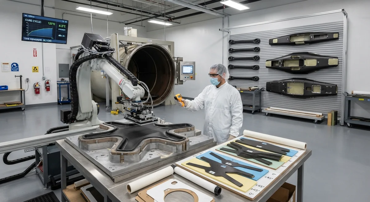
A technical analysis of carbon fiber structural design for last-mile delivery drones — covering airframe weight optimization, payload bay integration, impact resistance, and cost-volume production considerations for B2B buyers.
Introduction: The Structural Challenge of Last-Mile Delivery Drones
The global drone delivery market is projected to reach USD 39.0 billion by 2030, with last-mile logistics accounting for 55–60% of total drone operations. At the heart of every commercial delivery drone lies a fundamental engineering trade-off: maximizing payload capacity while minimizing airframe weight to extend range and endurance. Carbon fiber reinforced polymer (CFRP) composites have become the dominant structural material for mid-to-large delivery drones (5–30 kg MTOW), offering a strength-to-weight ratio 4–6× higher than 6061-T6 aluminum and fatigue endurance exceeding 10,000 flight cycles without degradation.
This article examines CFRP structural design for last-mile logistics drones from a B2B procurement perspective — covering airframe architecture, payload integration, manufacturing processes, and cost analysis for volume production. For logistics operators and OEMs evaluating carbon fiber drone structures, understanding these design parameters is essential for selecting the right structural configuration and manufacturing partner.
Airframe Architecture and Weight Optimization
Delivery drones typically employ one of three airframe architectures: quadrotor (4-rotor), hexacopter (6-rotor), or VTOL fixed-wing hybrid. Each imposes distinct structural requirements on the carbon fiber airframe. The primary structural components — central fuselage, motor arms/booms, landing gear, and payload bay — are almost exclusively manufactured from carbon fiber composites in modern commercial designs.
| Component | Material | Weight (kg) | CFRP Weight (kg) | Weight Saving | Cost Premium |
|---|---|---|---|---|---|
| Central fuselage frame (hexacopter, 15 kg MTOW) | 6061-T6 Al | 1.8–2.2 | 0.7–0.9 | 58–62% | +35–50% |
| Motor arms ×6 (each 450 mm) | 6061-T6 Al | 1.2–1.5 | 0.4–0.6 | 55–65% | +40–55% |
| Landing gear skids | Steel/Al | 0.5–0.7 | 0.15–0.25 | 60–70% | +25–35% |
| Payload bay enclosure | ABS/Polycarb | 0.4–0.6 | 0.12–0.18 | 65–72% | +50–70% |
| Total airframe (15 kg MTOW hexacopter) | 3.9–5.0 | 1.4–1.9 | 60–65% | +38–52% |
Structural Design Considerations
- Arm-to-fuselage joints: The arm attachment points experience peak bending moments during landing impact (3–6g). CFRP arms are typically bonded with aerospace-grade epoxy adhesive and mechanically fastened with 4–6 titanium M4 bolts per joint. Joint design must achieve a minimum safety factor of 2.0 at ultimate load.
- Battery compartment integration: Lithium-polymer battery packs (typically 6S–12S, 5–12 Ah) generate significant heat during discharge. CFRP battery bays require integrated ventilation channels or passive heat-sink features molded into the layup. Localized temperature resistance up to 80°C continuous must be verified for the resin system.
- Vibration damping: CFRP arm structures transmit motor vibration (50–200 Hz) more efficiently than aluminum due to lower damping ratio (CFRP ζ=0.3–0.5% vs Al ζ=0.8–1.5%). Passive damping layers — silicone or butyl rubber inserts — are often co-cured into the arm layup at critical nodes.
- RF transparency: For drones relying on RTK-GPS and telemetry, the fuselage section housing GPS antennas and flight controllers must maintain RF transparency below 2.4 GHz. This is achieved by using a thin fiberglass outer ply (0.2 mm) or a Kevlar hybrid layer over the carbon structure in the antenna zone.
Payload Delivery Mechanism Integration
The payload delivery system — typically a winch, drop-release mechanism, or lockbox — must be integrated into the CFRP airframe without compromising structural integrity. Three common delivery configurations exist: belly-mounted winch (2–5 kg capacity), internal cargo bay (5–15 kg capacity), and external pod attachment (up to 30 kg capacity).
- Winch integration: Belly-mounted electric winches (50–200 W, 0.5–2 m/s descent rate) require a hardpoint embedded in the fuselage floor. CFRP hardpoints use localized unidirectional carbon layup (plies oriented at 0°/90° with ±45° shear plies) and are co-cured with 1.5 mm aluminum or stainless steel thread inserts.
- Cargo bay door mechanism: Bottom-hinged CFRP doors must withstand landing loads and maintain dimensional stability across temperature ranges (−10°C to +55°C). Honeycomb-core CFRP sandwich panels (3 mm skins, 8 mm Nomex core) provide the required stiffness-to-weight ratio while minimizing deflection under aerodynamic pressure loads.
- Load cell integration: CFRP cargo floors often incorporate embedded load cells or strain-gauge bridges for real-time payload weight verification. Calibrated CFRP flexure elements — precision-machined from unidirectional tape — provide a linear strain response up to 3,000 microstrain at 100% rated load.
Manufacturing Processes for Volume Production
For delivery drone production volumes of 500–10,000 units per year, three CFRP manufacturing processes compete for the airframe contract: prepreg autoclave molding, resin transfer molding (RTM), and compression molding of sheet molding compound (SMC). Each offers a different balance of mechanical performance, cycle time, and tooling cost.
| Process | Cycle Time (per part) | Tooling Cost | Fiber Volume Fraction | Surface Finish | Recommended Volume |
|---|---|---|---|---|---|
| Prepreg Autoclave | 4–8 hours | $5,000–$15,000 | 60–65% | Excellent (Class A) | 500–2,000/yr |
| RTM (Resin Transfer Molding) | 15–40 min | $20,000–$60,000 | 55–60% | Good | 1,000–10,000/yr |
| Compression SMC | 3–8 min | $8,000–$25,000 | 45–55% | Fair | 5,000–50,000/yr |
Cost Analysis for B2B Buyers
Total airframe cost per unit scales inversely with production volume. At 1,000 units/year, the CFRP airframe for a 15 kg MTOW hexacopter costs approximately $380–$520 per unit (compared to $240–$310 for aluminum). At 10,000 units/year, CFRP costs drop to $190–$280 per unit — approaching cost parity with aluminum while offering 60% weight savings that translate directly to longer flight times, higher payloads, or reduced battery requirements.
- Material cost breakdown: Carbon fiber fabric (3K twill 200 gsm) accounts for 35–42% of total airframe cost; epoxy resin systems 8–12%; core materials (foam, Nomex) 6–10%; labor 20–30%; overhead and tooling amortization 15–25%.
- NDT requirements: Commercial drone CFRP structures typically require ultrasonic A-scan inspection at critical joints (20–40% of parts) and visual/TAP (tap-test) inspection for all parts. Full C-scan adds $15–$25 per airframe but is only required for defense-grade or FAA-certified drones.
- Minimum order quantities: Custom CFRP tooling amortization (2–5 years) drives minimum economic orders to 200–500 units per configuration. Modular tooling design — where common fuselage tools accept different arm geometries — can reduce MOQ to 100 units.
Frequently Asked Questions
What carbon fiber grade is recommended for delivery drone arms?
For motor arms, standard modulus (230 GPa) T700S-class carbon fiber in unidirectional prepreg tape is preferred. The 0° fiber orientation along the arm axis provides the necessary bending stiffness (EI ≥ 300 N·m² for a 450 mm arm at 15 kg MTOW). Intermediate modulus fibers (T800, 295 GPa) are rarely justified for delivery drones — the 28% stiffness increase comes at a 60–80% material cost premium. For fuselage shells and non-structural fairings, 3K or 6K plain weave fabric (200–240 gsm) in epoxy prepreg provides adequate strength at lower cost.
How does carbon fiber airframe cost compare to aluminum at production scale?
At 500 units/year, CFRP costs 50–65% more than equivalent 6061-T6 aluminum structures. At 5,000 units/year, the premium narrows to 25–35%. At 20,000+ units/year, RTM and compression molding processes achieve cost parity with CNC-machined aluminum — and when the battery weight savings from a lighter airframe are factored in (1 kg airframe weight reduction saves $50–$80 in battery cost), CFRP often achieves lower total system cost even at moderate volumes. The crossover point varies by airframe complexity but typically occurs between 3,000–8,000 units per year.
What certification standards apply to delivery drone CFRP structures?
For commercial drone operations, the most relevant standards include ASTM D6415 (curved beam strength), ASTM D7136 (drop-weight impact resistance), and IEC 60068-2 (environmental testing for vibration, temperature, and humidity). For FAA Part 135 drone delivery operators, additional structural certification per ASTM F3201 (unmanned aircraft composite structures) may apply. The European EASA has proposed specific MOC (Means of Compliance) for medium-risk drone composite structures under Delegated Regulation (EU) 2019/945. Most commercial delivery drone manufacturers target a minimum ultimate load safety factor of 2.0 and a fatigue life of 10,000 flight cycles without detectable damage propagation.
Part of topic
Related Articles
- Carbon Fiber Mooring for Floating Offshore Wind: Fatigue and Corrosion in Deep Water
- Carbon Fiber Bicycle Frame Optimization: Layup Design and Manufacturing for Competitive Racing
- Carbon Fiber CFRP Retrofit for Infrastructure: Bridge and Building Seismic Strengthening
- Carbon Fiber Medical Imaging Equipment: Lightweight Gantry and Couch Structures for MRI/CT
- Carbon Fiber EV Battery Enclosures: Crash Safety and Electromagnetic Shielding Design
- Carbon Fiber Structures for Low-Altitude Economy: UAV Airframes and eVTOL Components
Interested in Our Products?
Contact our team for competitive pricing and technical specifications.
Get a QuoteRelated Products

Carbon fiber standard plate-3k stripe
Lightweight, ultra-rigid standard sheets for drone fuselages, robot housings, facades and structural applications.

Carbon Fiber Plate — 3K Twill T700 1.5mm
Thin 1.5mm carbon fiber plate with 3K twill weave surface. Lightweight and stiff, commonly used for covers, panels, drone bodies, and applications requiring a premium aesthetic appearance.

Square Carbon Fiber Tube — 3K Twill T700
Square cross-section carbon fiber tube manufactured with 3K twill weave for torsional strength. Preferred for structural frames, trusses, and support columns where rectangular geometry offers design flexibility.

Carbon Fiber Plate — 3K Twill T700 3.0mm
Medium-thickness 3.0mm carbon fiber plate offering significantly higher load capacity while maintaining attractive 3K twill finish. Suitable for structural brackets, reinforcement plates, and load-bearing panels.

Carbon Fiber Plate — UD Unidirectional T700
Unidirectional carbon fiber plate with all fibers oriented in a single direction for maximum strength along the fiber axis. Essential for structural reinforcements, splints, and applications where load direction is predictable.