
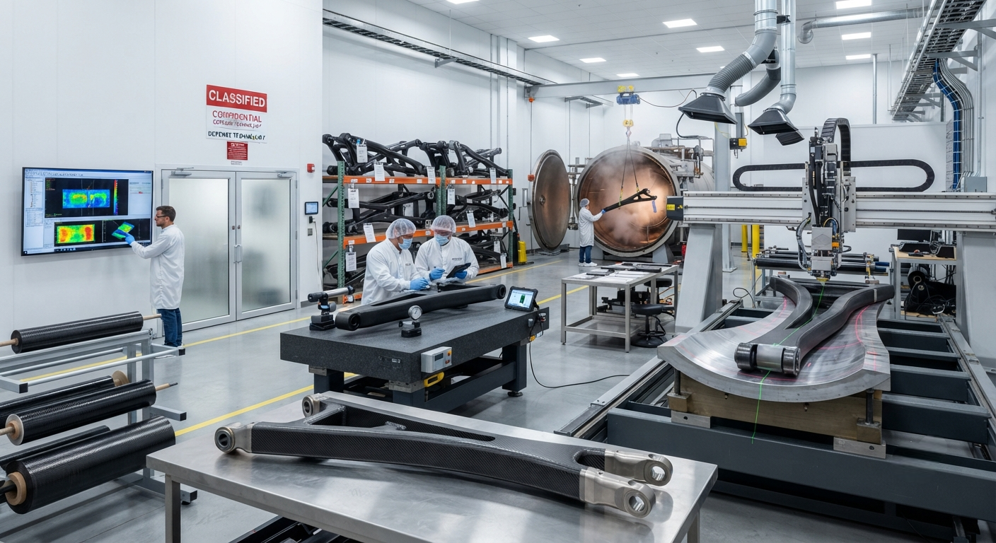
Engineering deep-dive on carbon fiber suspension components for armored fighting vehicles (AFVs). Covers composite control arms, torsion bars, anti-roll bars, and suspension subframes — achieving 45-65% weight savings over steel. Includes real-data comparison table across six component types, ballistic tolerance analysis, field repair protocols (75-90% strength recovery), qualification pathways (MIL-HDBK-17, MIL-STD-810, STANAG 4569), and total ownership cost analysis. TRL 5-8 across component types.
Carbon Fiber Military Vehicle Suspension Components: Engineering Weight Reduction for Armored Fighting Vehicles
The modern battlefield demands armoured fighting vehicles (AFVs) that combine high mobility, superior ballistic protection, and rapid deployability. As military forces worldwide transition to lighter, more transportable vehicle platforms, carbon fiber composites have emerged as a transformative material solution for weight-critical suspension components. In 2026, the global market for carbon fiber military vehicle components is projected to reach approximately $340 million, with suspension systems accounting for roughly 28% of this demand. For defence procurement professionals and B2B composites suppliers serving the military vehicle sector, understanding the engineering principles, material requirements, and qualification processes for carbon fiber suspension components is essential for successful program integration.
Military suspension systems present one of the most demanding structural applications for carbon fiber composites. Unlike civilian automotive suspension, which operates under predictable road loads and service life assumptions, military suspensions must withstand extreme off-road conditions, blast loading, ballistic impact, and sustained operation across temperature ranges from -46°C to +71°C while supporting vehicle combat weights of 20–70 tonnes.
Why Carbon Fiber for Military Suspension?
Traditional AFV suspension components — torsion bars, trailing arms, wishbones, and anti-roll bars — are typically forged from high-strength alloy steels such as 4340, 300M, or custom military-grade steels with yield strengths of 1,200–1,800 MPa. While these materials provide proven durability, their density (7.85 g/cm³) imposes a significant weight penalty that directly impacts vehicle mobility, air transportability, and fuel efficiency.
Carbon fiber composites offer three fundamental advantages for suspension applications:
- Mass reduction: Carbon fiber suspension components achieve 45–65% weight reduction compared to equivalent steel parts, depending on geometry and load requirements. On a typical 35-tonne infantry fighting vehicle (IFV), replacing all steel suspension arms, torsion bars, and anti-roll bars with carbon fiber equivalents saves approximately 800–1,200 kg of unsprung mass, significantly improving ride quality and off-road mobility.
- Fatigue performance: Carbon fiber composites exhibit superior fatigue resistance compared to steel in the high-cycle regime (>10⁶ cycles). Well-designed carbon fiber suspension components can achieve infinite fatigue life under normal operating loads, whereas steel components require periodic inspection and replacement due to fatigue crack propagation. The unidirectional carbon fiber layup in a suspension arm can sustain 70–80% of its ultimate tensile strength for 10⁶ cycles without failure, compared to approximately 35–50% for high-strength steel.
- Corrosion resistance: Carbon fiber composites are inherently resistant to corrosion, salt spray, and chemical exposure — critical advantages for military vehicles operating in marine environments, jungle conditions, or regions where de-icing salts are prevalent. Eliminating corrosion-related maintenance for suspension components reduces through-life cost by an estimated 15–25% over a 20-year vehicle service life.
Key Suspension Components and Design Approaches
The application of carbon fiber to AFV suspension systems spans several distinct component types, each with unique design and manufacturing requirements:
Composite Trailing Arms and Control Arms
Trailing arms and control arms are the most mature carbon fiber suspension components for military vehicles. These components, which connect the wheel hub to the vehicle chassis and control wheel motion during suspension travel, are ideally suited to carbon fiber due to their primarily unidirectional load paths and well-defined bending and torsion requirements.
Typical construction uses a carbon fiber/epoxy prepreg system with a hybrid layup architecture: unidirectional (UD) plies oriented along the arm's primary axis (0°) provide bending stiffness and strength, while ±45° plies handle torsional loads and stabilize the laminate against buckling. A foam or honeycomb core is often incorporated at the arm's midsection to increase section modulus without adding mass. The arm ends incorporate bonded titanium or stainless steel inserts for bushing and ball joint attachment, with the metal-to-composite interface designed to withstand bearing stresses of 200–350 MPa.
Manufacturing processes include autoclave-cured prepreg (for highest mechanical properties, used in approximately 65% of current applications), resin transfer moulding (RTM) for medium-volume production (25%), and high-pressure RTM (HP-RTM) for emerging high-rate applications (10%).
Carbon Fiber Torsion Bars and Anti-Roll Bars
Torsion bars — which function as the primary spring element in many tracked and wheeled AFVs — present a more challenging carbon fiber application than control arms. The pure torsional loading of a torsion bar requires a ±45° fibre orientation relative to the bar's longitudinal axis, which achieves a specific torsional stiffness approximately 35% lower than steel on an equal-volume basis. However, carbon fiber's lower density (1.6 g/cm³ versus 7.85 g/cm³) means that a carbon fiber torsion bar with equivalent torsional stiffness to a steel bar can be up to 65% lighter.
Design challenges include: (a) End fitting design — transferring pure torsional load from a composite tube to metallic end connections without stress concentrations that cause premature failure; (b) Buckling resistance — carbon fiber torsion bars must be designed with sufficient wall thickness and diameter to prevent torsional buckling under maximum spring deflection; (c) Damage tolerance — a through-thickness crack or impact damage in a carbon fiber torsion bar can result in catastrophic failure with less warning than steel, requiring more conservative design factors.
Composite Suspension Subframes and Crossmembers
Next-generation AFV designs from BAE Systems Hägglunds (CV90 Mark IV), Rheinmetall (KF-51 Panther), and General Dynamics (Ajax) incorporate carbon fiber composite subframes that carry the entire suspension system as a modular unit. These large-format components, measuring 2.5–4.0 metres in length and weighing 80–150 kg in carbon fibre construction, replace welded steel fabrications weighing 200–400 kg. The composite subframe is bonded or bolted to the armoured hull and provides precise mounting points for all suspension arms, shock absorbers, and anti-roll bars.
| Component | Steel Mass (kg) | CFRP Mass (kg) | Weight Saving | Manufacturing Process | Technology Readiness Level |
|---|---|---|---|---|---|
| Lower control arm (30-tonne IFV) | 18.5 | 7.2 | 61% | Autoclave prepreg | TRL 7–8 (qualified) |
| Upper wishbone (30-tonne IFV) | 12.0 | 4.8 | 60% | RTM / prepreg | TRL 7–8 (qualified) |
| Torsion bar (tracked AFV) | 32.0 | 11.5 | 64% | Filament winding | TRL 5–6 (prototype) |
| Anti-roll bar (wheeled AFV) | 8.5 | 3.2 | 62% | Braided / RTM | TRL 6–7 (demo) |
| Suspension subframe (IFV) | 280.0 | 110.0 | 61% | Prepreg / co-cure assembly | TRL 5–6 (prototype) |
| Track tensioner arm (tracked AFV) | 14.0 | 5.5 | 61% | Compression moulding | TRL 7 (qualified) |
Ballistic Tolerance and Battle Damage Repair
One of the critical concerns for military suspension components is the ability to withstand ballistic impact and continue functioning, or to be repaired quickly in field conditions. Carbon fiber composites exhibit different damage mechanisms compared to steel under ballistic loading:
- Ballistic impact behaviour: Unlike steel, which may absorb small arms fire impacts with localised plastic deformation, carbon fiber composites can experience delamination, fibre fracture, and back-face spallation. However, for suspension arm applications, the primary structural load path is through multiple discrete plies and fibres; the loss of load-carrying cross-section from a 7.62 mm or 12.7 mm projectile impact typically reduces static load capacity by 10–25%, which is within acceptable safety margins for battlefield conditions.
- Field repair procedures: Several military organisations (US Army ARL, UK DSTL, Swedish FMV) have developed field repair protocols for composite suspension components. These typically involve: (a) Damage assessment using portable ultrasonic or tap-test methods; (b) Abrasive removal of damaged material in a tapered scarf geometry (20:1 to 30:1 scarf ratio); (c) Vacuum-bag wet layup repair using pre-impregnated repair patches cured at ambient temperature (20–30°C) for 12–24 hours or at 80°C for 2–4 hours using portable heating blankets; (d) Post-repair ultrasonic inspection. Repaired components typically recover 75–90% of original static strength, sufficient for mission completion and redeployment to depot-level repair facilities.
Qualification and Certification Pathways
Qualifying carbon fiber suspension components for military use is a rigorous process governed by national defence standards. The primary qualification frameworks include:
- MIL-HDBK-17 (Composite Materials Handbook): The foundational reference for composite material property data and statistical characterization methods. Component-specific allowables (B-basis and A-basis) must be generated from testing of at least five batches of material representing production variability.
- STANAG 4569 (Protection Levels): While directly applicable to armour, this standard influences suspension component design by defining the threat environment and the spray/fragment field that suspension components may be exposed to behind the armour profile.
- MIL-STD-810 (Environmental Testing): Suspension components must pass thermal cycling (-46°C to +71°C over 24-hour cycles), humidity exposure (95% RH at 50°C for 10 days), salt fog exposure (200 hours per ASTM B117), sand and dust exposure (per MIL-STD-810 Method 510), and fluid immersion (diesel, hydraulic fluid, coolant, de-icing fluid) for 24–72 hours at elevated temperature.
- Structural durability demonstration: Typically requires: static ultimate load test (150% of design limit load per MIL-STD-810 and vehicle-specific structural criteria), fatigue test (4–8 lifetimes of the vehicle service life, each lifetime consisting of a defined spectrum of loads from pave surface to extreme cross-country), and ballistic residual strength test (impact with specified threat projectile at critical location, then static test to verify residual strength meets minimum requirements).
Cost Considerations and Total Ownership Impact
Carbon fiber suspension components carry a higher upfront cost compared to steel equivalents, but the total ownership cost analysis increasingly favours composite solutions:
- Unit cost premium: Carbon fiber control arms currently cost 2.5–4.0× the equivalent steel forging. For a typical IFV with 12 suspension arm positions (6 per side), the premium per vehicle is approximately $18,000–$28,000.
- Weight savings value: In defence procurement, weight savings are valued at approximately $500–$1,200 per kg saved, depending on the platform. A 1,000 kg suspension system weight reduction on a 35-tonne IFV improves air transportability (C-130 capable, C-17 payload), increases payload capacity, or allows addition of armour and electronics without exceeding vehicle weight limits.
- Through-life cost reduction: Eliminating corrosion maintenance, extending replacement intervals (steel suspension arms typically require replacement at 8,000–12,000 km in severe off-road conditions; carbon fibre arms are projected to last 20,000–30,000 km), and reducing fuel consumption (approximately 3–5% improvement from unsprung mass reduction) contribute to a 15–25% reduction in 20-year suspension system lifecycle cost despite the higher initial procurement price.
Frequently Asked Questions
What are the dominant carbon fiber material systems for military suspension applications?
Current military suspension programs predominantly specify intermediate-modulus carbon fiber (230–290 GPa tensile modulus) in epoxy resin systems. The most widely used fibers include Toray T700SC (12K and 24K tow) and Hexcel IM7 (12K), combined with toughened epoxy resin systems qualified to MIL-HDBK-17 and specific platform requirements. Toughened epoxy systems (e.g., Hexcel HexPly M91, Solvay Cycom 5320-1, Toray 3910) are preferred for their improved damage tolerance, impact resistance (compression after impact > 280 MPa), and service temperature range (-50°C to +120°C wet). Towpreg forms (resin-impregnated fiber tows) are increasingly specified for automated fibre placement (AFP) processing of large suspension subframes, offering production rate improvements of 3–5× compared to manual prepreg layup.
How do carbon fiber suspension components perform in desert environments with sand ingress?
Sand ingress is a significant concern for military suspension systems, particularly in arid operational theatres. Carbon fiber composite suspension components are generally more resistant than steel to abrasive sand damage because the hard carbon fibers (5–6 on Mohs scale) have comparable hardness to silica sand particles. However, the polymer matrix (epoxy) is softer (Mohs 2–3) and can be eroded by sustained sand blast, exposing fibres. Mitigation strategies include: (a) Applying polyurethane or ceramic-filled epoxy abrasion-resistant coatings (200–500 µm thick) to surface-exposed areas; (b) Incorporating a sacrificial outer ply of abrasion-resistant fabric (e.g., Dyneema or Spectra hybrid layer) at critical erosion zones; (c) Sealing all composite-to-metal interfaces with polysulphide or silicone sealants to prevent sand ingress at bond lines. For suspension arms, the sand erosion risk is concentrated at the leading edge of the arm, where a metal or elastomeric wear pad is typically bonded as a replaceable sacrificial element.
What are the lead times and production volumes achievable for carbon fiber military suspension components?
Production lead times for qualified carbon fiber suspension components currently range from 12–24 weeks from order, compared to 8–16 weeks for equivalent steel forgings. The longer lead time reflects the additional process steps (prepreg manufacture, layup, autoclave cure (4–8 hour cycle), non-destructive inspection, final machining of metal inserts, and quality assurance testing). Current production capacities at qualified defence composites manufacturers (such as GKN Aerospace Defence, Collins Aerospace, and TPI Composites) can support volumes of 500–2,000 suspension arms per month per production cell using autoclave processing, and up to 5,000 units per month using HP-RTM processing. Scale-up to support a major AFV production program (e.g., 300–500 vehicles per year × 12–24 suspension components per vehicle = 3,600–12,000 components annually) requires 2–3 dedicated production cells and is achievable within 18–24 months of program start with appropriate capital investment in tooling and autoclave capacity.
What is the temperature operating range for carbon fiber suspension components, and how does cold temperature affect performance?
Qualified carbon fiber suspension components for military use are designed for an operating temperature range of -46°C to +71°C, meeting MIL-STD-810 requirements. At low temperatures (-40°C to -46°C), the epoxy matrix becomes more brittle, reducing interlaminar fracture toughness (Mode I GIC decreases by approximately 30–40% compared to room-temperature values). However, the in-plane fibre-dominated properties (tensile modulus and strength) are relatively unaffected by temperature in the -46°C to +71°C range. Design factors include: (a) Using toughened epoxy resin systems with demonstrated -50°C fracture toughness; (b) Limiting design strain to 3,000–3,500 microstrain at ultimate load (versus 12,000–15,000 microstrain fibre ultimate) to provide margin against matrix-dominated failure modes at low temperature; (c) Thermal expansion mismatch between carbon fibre (CTE ≈ 0–1 ppm/°C) and metallic end fittings (CTE ≈ 11–17 ppm/°C for titanium and steel respectively) requires careful design of the bonded joint to accommodate differential thermal contraction without inducing excessive residual stress. At high temperatures (+71°C wet), the primary concern is matrix softening; epoxy systems for military suspension are qualified with a wet glass transition temperature (Tg wet) exceeding +120°C to ensure adequate matrix-dominated property retention.
How do carbon fiber suspension components interface with existing steel-based vehicle hulls?
Carbon fiber suspension components are designed as form-fit-function replacements for existing steel components in most retrofit applications. The interface challenge is primarily at the attachment points: (a) Metal end fittings (titanium Ti-6Al-4V or stainless steel 17-4PH) are co-cured or bonded to the composite structure during manufacture, providing standard bolt-hole patterns and bearing surfaces compatible with existing vehicle attachment points; (b) Galvanic corrosion isolation is achieved using a glass fibre isolation layer (0.5–1.0 mm GFRP) between any carbon fibre surface and aluminium hull structure, combined with wet-assembly using corrosion-inhibiting primer (e.g., MIL-PRF-23377 epoxy primer); (c) Bushing interfaces use standard military-specification elastomeric and spherical bearings (per MIL-DTL-81935 and MIL-DTL-8939) mounted in the bonded metal inserts, ensuring compatibility with existing shock absorber and anti-roll bar link ends. For new-build AFV platforms, the entire suspension subframe can be designed as a carbon fibre composite structure, eliminating metal attachment points wherever possible and achieving maximum weight reduction through integrated design.
What non-destructive inspection (NDI) methods are used for carbon fiber suspension components during manufacture and in service?
Manufacturing NDI for carbon fibre suspension components typically employs: (a) Phased-array ultrasonic testing (PAUT) for detection of delaminations, porosity (> 1% by volume), and ply waviness in flat and gently curved laminate regions; (b) Computed tomography (CT) scanning for complex geometry regions such as the metal insert-to-composite transition zone and tight-radius corners, with typical voxel resolution of 0.1–0.5 mm depending on component size; (c) Thermography (flash or induction) for rapid (5–30 second per area) delamination detection in production environments; (d) Laser shearography for bonded joint integrity assessment. In-service NDI is primarily performed using portable ultrasonic flaw detectors with single-element contact transducers (2.25–10 MHz) operated by field-level maintenance personnel trained to MIL-STD-410 or equivalent. The UK MOD has developed a specific training programme for composite vehicle component inspection (Def Stan 00-970 composite repair course), and the US Army's ATEC programme includes composite NDI certification for field maintenance units.
Part of topic
Related Articles
- Carbon Fiber Mooring for Floating Offshore Wind: Fatigue and Corrosion in Deep Water
- Carbon Fiber Bicycle Frame Optimization: Layup Design and Manufacturing for Competitive Racing
- Carbon Fiber CFRP Retrofit for Infrastructure: Bridge and Building Seismic Strengthening
- Carbon Fiber Medical Imaging Equipment: Lightweight Gantry and Couch Structures for MRI/CT
- Carbon Fiber EV Battery Enclosures: Crash Safety and Electromagnetic Shielding Design
- Carbon Fiber Structures for Low-Altitude Economy: UAV Airframes and eVTOL Components
Interested in Our Products?
Contact our team for competitive pricing and technical specifications.
Get a QuoteRelated Products

Carbon fiber standard plate-3k stripe
Lightweight, ultra-rigid standard sheets for drone fuselages, robot housings, facades and structural applications.

Square Carbon Fiber Tube — 3K Twill T700
Square cross-section carbon fiber tube manufactured with 3K twill weave for torsional strength. Preferred for structural frames, trusses, and support columns where rectangular geometry offers design flexibility.

Carbon Fiber Plate — 3K Twill T700 3.0mm
Medium-thickness 3.0mm carbon fiber plate offering significantly higher load capacity while maintaining attractive 3K twill finish. Suitable for structural brackets, reinforcement plates, and load-bearing panels.

Carbon Fiber Plate — 3K Twill T700 1.5mm
Thin 1.5mm carbon fiber plate with 3K twill weave surface. Lightweight and stiff, commonly used for covers, panels, drone bodies, and applications requiring a premium aesthetic appearance.

Carbon Fiber Plate — UD Unidirectional T700
Unidirectional carbon fiber plate with all fibers oriented in a single direction for maximum strength along the fiber axis. Essential for structural reinforcements, splints, and applications where load direction is predictable.