
Liquefied natural gas (LNG) is shipped and stored at its boiling point of −162°C, and liquid hydrogen (LH2) is handled at −253°C, only twenty degrees above absolute zero. At these temperatures, the temperature difference between the cargo and the ambient environment drives a continuous
Introduction
Liquefied natural gas (LNG) is shipped and stored at its boiling point of −162°C, and liquid hydrogen (LH2) is handled at −253°C, only twenty degrees above absolute zero. At these temperatures, the temperature difference between the cargo and the ambient environment drives a continuous inward heat leak that boils off cargo — product lost, energy wasted, and in the case of hydrogen, a safety consideration. The insulation system therefore has two jobs at once: minimize the heat flux into the cryogenic fluid, and carry the structural loads of the tank, the cargo, and the temperature gradient itself without cracking or leaking.
Carbon fiber composite sandwich panels have become a leading answer to this dual requirement in large-scale LNG and hydrogen infrastructure, from membrane-type LNG carrier tanks to the primary insulation of advanced hydrogen storage concepts. This article covers the physics of cryogenic heat transfer, the material selection inside a sandwich panel, the thermal break problem at panel edges, and the qualification testing that governs the panel design for both LNG carriers and hydrogen applications.
Heat Leak in Containment Systems
At cryogenic temperatures the mechanisms that move heat into a tank differ meaningfully from common engineering experience. Three heat transfer modes matter in containment systems:
| Heat transfer mechanism | Dominant in | Typical role in insulation design |
|---|---|---|
| Conduction through solid structure | Thermal anchor points, tank supports, pipes | Drives need for thermal breaks and low-conductivity supports |
| Convection inside insulation cavities | Gas-filled foam cavities, air gaps | Inhibit it by vacuum, pressurized gas, or small-diameter pores |
| Radiation between warm and cold surfaces | Vacuum multilayer insulation (MLI) | Handled with reflective radiation barriers in high-performance vessels |
For membrane-type LNG tanks — the dominant technology for large LNG ships — the insulation is not purely vacuum but a combination of foam and mastic materials retaining a nitrogen gas atmosphere. The carbon fiber sandwich panel fits this system when it acts as a structural back-up structure to support the membrane and to transfer loads into the hull, while the foam core provides insulation.
Carbon Fiber Sandwich Panel Construction
A carbon fiber sandwich panel is a laminate "face sheet" of carbon fiber reinforced polymer bonded to both sides of a lightweight core. For cryogenic use, the face sheets carry the structural loads, while the core adds moment-of-inertia with minimum weight and provides the bulk of the thermal resistance. Face and core properties pull the design in opposite directions, and the natural selection depends on the application:
| Core material | Density (kg/m³) | Thermal conductivity (W/m·K at 20°C) | Typical use in cryo |
|---|---|---|---|
| Closed-cell polyurethane foam | 140-250 | 0.020-0.030 | Membrane tank secondary insulation |
| PVC structural foam | 80-250 | 0.030-0.045 | Primary insulation of tanks |
| PI (polyimide) foam | 100-250 | 0.030-0.050 | LH2 applications, higher temperature tolerance |
| Balsa wood | 150-350 | 0.050-0.070 | Legacy LNG platforms, high compressive profile |
Fiber-reinforced face sheets give the panel structural strength up to the face sheet material's capability at cryogenic temperature. Carbon fiber reinforced polymer is particularly attractive at cryogenic temperature because its tensile properties improve when cooled — the fibers and matrix both gain strength and elastic modulus into the cryogenic regime. The thermal contraction of the laminate is small and tailorable with fiber orientation — a face sheet with a high axial fiber fraction (0° dominated) achieves essentially no thermal deformation along the panel direction, which is one of the primary qualification metrics of these panels.
Thermal Mechanical Behavior at Cryogenic Temperature
The most demanding part of cryogenic composite design is not the pure cold, but the combination of cold, differential thermal contraction, and the transit of vaporization fronts during loading and unloading.
- Thermal contraction mismatches in a panel assembly: The sandwich laminate contracts slightly (CTE ≈ −0.5 to 0.5 × 10⁻⁶/°C longitudinal), while the metal (e.g., stainless steel or invar) parts of the mating connect have positive CTE of 10-16 × 10⁻⁶/°C. This mismatch is the mechanism that drives stress into both bonding lines at glued joints and thermal breaks.
- Resin microcracking: Epoxy matrix resins become brittle below approximately −60°C; thermal cycling to −162°C or −253°C shrinks the matrix around the fibers and can produce microcracks. Expected test methods therefore cycle panels hundreds of times and inspect for microcrack density, which is the core acceptance criterion for cryogenic composite.
- Vaporization front movement: During charge of a cold tank, the level and temperature field moves quickly; the panel experiences a moving temperature gradient. It is tested by applying sudden thermal shock to the cold side while keeping the warm side at ambient temperature.
For LH2 at −253°C, the thermal margin is much smaller than LNG — LH2 absorbs a lot of energy before boiling (heat capacity), which raises the effort of the thermal barrier design. Polyimide face resins and polyimide cores are the standard approach for hydrogen service because of their wider usable temperature range and lower microcracking at very low temperature.
Thermal Break Design at Panel Edges and Supports
The single most neglected source of heat leak in cryogenic structures is conduction through metallic structural paths — the flanges, the support pads, the hold-down bolts at the panel edges and supports. Even a small steel cross-section becomes a "thermal short" that bypasses the entire insulation stack. The composite sandwich panel has a structural advantage here: it can be designed so that all load paths through the panel are composite. When metallic fasteners are unavoidable, thermal breaks are conservative designs:
- Composite studs and fasteners: pultruded carbon fiber or glass fiber studs replace steel studs where load permits, cutting heat leak through the fastener by 90%+.
- Thermally isolated base plates: the metallic plate is reduced to a thin layer separated from the panel surface by low-conductivity board/shim spacers — cutting the thermal foot at the connection.
- Edge framing: sandwich panels are placed with minimum edge gap caulked with cryogenic-class mastic to prevent an open convection channel along the panel edge.
- Double-wall anchor design: supports are routed through secondary thermal ring baffles so that the largest thermal flux is transferred in stages, and the panel edge stays below the dew point.
The thermal break becomes a complete system — and a carbon fiber support is often lighter and has lower conductive heat flow than its steel equivalent, which is beneficial for the total heat influx balance (boil-off reduction) of a carrier.
Structural Integrity and Testing
Cryogenic composite panels are qualified against a demanding test suite before use, because failure is not an option at cryogenic temperature with volatile cargo. The standard qualification stack includes:
- Thermal cycling (LNG): typically 500 thermal cycles between +20°C and −196°C on large test panels with multiple sensors (thermocouples) to check both thermal efficiency and structural integrity after each cycle window (e.g., after 300 and 500 cycles).
- Microcrack inspection: acoustic emission, ultrasonic scanning or dye penetration performed after cycling to quantify the microcrack density in the matrix and face sheets.
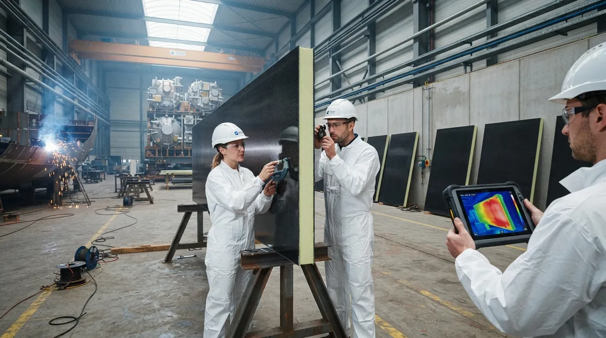
- Mechanical load tests at cold state: panel bending, edge compression and shear tests are repeated on the cold panel (in a cold chamber) to demonstrate that the structural stiffness is maintained at operating temperature.
- Thermal shock test: a sudden temperature drop following rapid charge is simulated by spraying LN2 onto one side of the panel while the other side remains at ambient; the panel must show no delamination or visible crack.
- Oxygen/flammability parameters: for hydrogen infrastructure the panels and adhesives are tested for hydrogen embrittlement and flammability compatibility per applicable ASME/ASTM standards.
Panel design acceptance is guided by the standards applicable to the tank type — IGC code for LNG membrane tanks, ASME BPV Code Section VIII for pressure vessels — and cryogenic vessels beyond class have individual approval and production oversight from the classification society (Lloyd's, DNV, ClassNK).
Cryogenic Insulation Test Mounting
Once a sandwich panel is designed and qualified, several installation details dominate real-world performance of these insulation systems:
- Controlled compression: foam cores (especially polyurethane) need a defined minimum compression so that they do not slip or contribute to load assumptions; the panels are shimmed and compressed with a calibrated torque on fasteners.
- Vapor-sealed enclosure: the utility foam is protected from moisture ingress that would add conductive ice and increase heat leak; the seams are vapor-locked with a sealant that remains crack-free at cryogenic temperature.
- Health monitoring of the system: cryogenic insulation failure is often detected only by slow boil-off checks in the tank; some systems add humidity/condensation (dew-point) sensors and thermocouple grids between two panel layers.
Seasonal and 30-year performance: the boil-off of a large LNG tank is controlled by total insulation system integrity; panels (per system) are specified with redundancy and designed for 30-40 year outcomes for LNG carrier hull tanks.
Frequently Asked Questions
Why is carbon fiber used in cryogenic insulation at all when foam is the insulator?
Two separate needs exist: heat insulation (which foam and the core serve) and structural integrity (which carbon fiber panels provide). In a membrane LNG tank the entire tank content is held by an inner layer that must resist the static pressure of the cargo and the thermal contraction — and that inner structural layer is a must for the safety of the cargo at very low temperature. Carbon fiber sandwich panels combine both: the composite face sheets carry the structural loads up to the cold operating temperature while the foam core performs passive insulation; compared to a metal inner layer covered by separate foam, the composite panel performs both functions with lower heat leak from the small fastening points and no metallic thermal anchors.
What is the operating temperature limit of a carbon fiber panel at the LH2 stage?
The primary limitation is not carbon fiber, but the matrix resin and the core at −253°C. Carbon fibers and most thermoset resins (epoxy, cyanate) remain operational down to −253°C; the issues at this extreme are mostly microcracking of the matrix under repeated thermal cycling and the embrittlement of the adhesive layers. Standard aerospace epoxy with cryogenic-optimized formulations can be qualified for LH2 service with careful layup design (higher fractions of 0° fibers to linearize contraction) and core selection (polyimide or cyanate-class foam). The standard qualification matrix includes 20 or more full thermal cycles down to −196°C for LNG service, plus additional verification down to −253°C using representative test coupons for hydrogen applications.
How much lower is the carbon fiber sandwich panel heat leak versus a steel-constructed system?
The exact figure depends on tank geometry, but in LNG membrane carriers the thermal leak of a composite panel system is typically 10-20% lower than a traditional metallic support system over the same insulation performance. Two effects drive this. First, the carbon face sheets have a thermal conductivity of roughly 5-30 W/m·K (against steel's 45 W/m·K), and they do not act as continuous thermal anchors the way a welded steel inner casing does. Second, the largest single source of stray heat in any cryogenic tank is the support structure: replace steel studs with carbon fiber studs at load-bearing points and the heat leak through those pins drops by a factor as high as 10, because the carbon-fiber stud carries the same load at roughly half the conductivity and half the cross-section for equivalent tensile capability. The type, size, and number of supports are the dominant variables, so a full heat-leak balance for the specific tank design always precedes the final figure.
Conclusion
Cryogenic insulation structures for LNG and hydrogen storage are a place where carbon fiber sandwich panels are more than a lightweight option — they are the standard for combining thermal and structural performance in membrane tanks. The panel brings face-sheet structural stiffness, low thermal contraction, and thermal breaks that can handle −253°C fuel cycles, while foam cores carry the actual insulation load. Because large infrastructure spends decades in service at cryogenic temperature, physical testing and qualification are as integral to the panel as any design decision — thermal cycling, microcrack control, and vapor sealing determine whether a panel is service- or ship-worthy.
For tank constructors, LNG carriers, shipyards and hydrogen infrastructure engineers, our carbon fiber sandwich panels and thermal break components are manufactured for cryogenic duty with CTE-tailored face sheet layups and qualification support from your class society. Contact our engineering team for panel sizing, thermal leak analysis, and testing support on your LNG or hydrogen project.
Part of topic
Related Articles
- Carbon Fiber Tube for Sale: Comparing Listings and Avoiding Bad Specs
- Carbon Fiber Engine Parts: High-Temperature Performance for Racing and Performance Vehicles
- Carbon Fiber Body Parts: Automotive Exterior Panels and Structural Components
- Carbon Fiber Drone Body Manufacturing: Monocoque Design and Production Methods
- Carbon Fiber Drone Parts Supplier: FPV Frames, Arms and Structural Components
- Filament Wound Epoxy Tubes: Industrial Applications from Oil and Gas to Aerospace
Interested in Our Products?
Contact our team for competitive pricing and technical specifications.
Get a QuoteRelated Products

Carbon fiber standard plate-3k stripe
Lightweight, ultra-rigid standard sheets for drone fuselages, robot housings, facades and structural applications.

Carbon Fiber Plate — 3K Twill T700 3.0mm
Medium-thickness 3.0mm carbon fiber plate offering significantly higher load capacity while maintaining attractive 3K twill finish. Suitable for structural brackets, reinforcement plates, and load-bearing panels.

Carbon Fiber Plate — 3K Twill T700 1.5mm
Thin 1.5mm carbon fiber plate with 3K twill weave surface. Lightweight and stiff, commonly used for covers, panels, drone bodies, and applications requiring a premium aesthetic appearance.

Square Carbon Fiber Tube — 3K Twill T700
Square cross-section carbon fiber tube manufactured with 3K twill weave for torsional strength. Preferred for structural frames, trusses, and support columns where rectangular geometry offers design flexibility.

Carbon Fiber Plate — UD Unidirectional T700
Unidirectional carbon fiber plate with all fibers oriented in a single direction for maximum strength along the fiber axis. Essential for structural reinforcements, splints, and applications where load direction is predictable.