
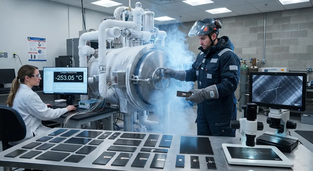
Cryogenic testing of carbon fiber composites is the discipline that separates hydrogen storage hardware that works from hardware that leaks, cracks, or bursts in service. Liquid hydrogen boils at −253°C, and carbon fiber reinforced polymers behave very differently at that temperature th
Introduction
Cryogenic testing of carbon fiber composites is the discipline that separates hydrogen storage hardware that works from hardware that leaks, cracks, or bursts in service. Liquid hydrogen boils at −253°C, and carbon fiber reinforced polymers behave very differently at that temperature than they do at room temperature. Matrix shrinkage, thermal stress, and microcrack formation are the dominant failure mechanisms, and every qualification program must prove that a composite structure survives them repeatedly.
This article covers the core test methods — cryogenic mechanical testing, thermal cycling, microcrack inspection, and permeation measurement — and explains what the results mean for material selection and tank qualification. It is written for engineers and technical buyers evaluating composite suppliers for liquid hydrogen storage, aircraft fuel systems, and aerospace propulsion programs.
Why Composites Degrade at Cryogenic Temperature
The behavior of a carbon fiber laminate at −253°C is governed by the mismatch between fiber and matrix. Carbon fibers have a near-zero or slightly negative coefficient of thermal expansion, while epoxy matrix systems contract significantly on cooldown. The result is a tensile stress state in the matrix that grows with every thermal excursion. Key degradation mechanisms include:
- Matrix microcracking: Thermal stress cracks the resin between fibers, creating networks of fine cracks that reduce shear transfer and open permeation paths.
- Fiber-matrix interface damage: Repeated contraction can debond the interface, lowering transverse strength and fatigue life.
- Resin embrittlement: Most epoxy systems become stiffer and more brittle at cryogenic temperature, reducing the strain-to-failure available before cracking.
- Fiber kinking and compression effects: Differential contraction can introduce local fiber waviness that degrades compressive performance.
Because these mechanisms interact, no single room-temperature test can predict cryogenic performance. A laminate that shows excellent strength at 23°C can lose 30-60% of its transverse and shear strength at −253°C, and can develop microcracks after only tens of thermal cycles. Qualification testing must therefore be performed at the actual service temperature, not extrapolated from ambient data.
Core Test Methods for Cryogenic Composites
Qualification of a cryogenic composite structure relies on a family of test methods, each addressing a specific failure mode. The table below summarizes the most common tests, what they measure, and typical acceptance criteria:
| Test Method | What It Measures | Typical Conditions | Acceptance Criterion |
|---|---|---|---|
| Tensile testing | 0° strength and modulus | −253°C, 1-2 mm/min | Retains ≥85% of ambient strength |
| Compression testing | 0° and 90° compressive strength | −253°C, modified Celanese fixture | No premature end-crushing failure |
| In-plane shear (Iosipescu) | Shear strength and modulus | −253°C, ±45° or V-notch | Shear retention documented vs ambient |
| Thermal cycling | Microcrack resistance over repeated excursions | 100-1,000 cycles, 20°C to −253°C | Microcrack density below 1-5 cracks/cm² |
| Microcrack inspection | Crack density and distribution | Edge replication, microscopy, CT | No through-thickness crack networks |
| Permeation testing | Gas leak rate through the laminate | Helium or hydrogen, 10⁻⁶-10⁻⁸ mbar·L/s | Below specification leak rate |
| Burst testing | Overall structural margin of a tank | 1.5-2.5× design pressure | Burst in cylindrical section, no dome failure |
Each test must be performed on specimens conditioned to the cryogenic state in a controlled manner. Soak times at −253°C typically range from 10 to 30 minutes to ensure the specimen core reaches equilibrium temperature before loading, and strain measurement requires cryogenic-rated extensometers or strain gauges.
Thermal Cycling: The Most Revealing Test
Thermal cycling between ambient temperature and −253°C is the test that most reliably exposes whether a composite system is truly cryogenic-capable. The strain imposed by each cycle is large — the epoxy matrix contracts roughly 1-2% over the full temperature range, while the fiber barely moves. When the matrix cannot accommodate this strain, microcracks appear.
For qualification, thermal cycling is usually performed in a gaseous helium or nitrogen environment with controlled ramp rates. The cycle profile matters as much as the temperature extremes:
- Ramp rate: Slow ramps of 2-10 K/min reduce thermal gradients and give more conservative data on intrinsic material resistance, while fast ramps better simulate rapid propellant loading.
- Dwell time: A 10-30 minute hold at −253°C ensures the laminate is fully saturated at the minimum temperature.
- Cycle count: Aerospace qualification programs commonly require 100-500 cycles; some programs for reusable vehicles specify up to 1,000.
- Inspection intervals: Specimens are typically inspected every 25-50 cycles to track crack density growth over time.
Microcrack density is usually quantified by edge replication or microscopy on polished edges, and increasingly by computed tomography for through-thickness crack mapping. A well-designed cryogenic material system shows stable, low crack density that does not grow with continued cycling, whereas a poor system shows progressive crack multiplication from the first cycles.
Material Properties at −253°C: What Changes
The table below compares typical room-temperature and cryogenic properties for a standard aerospace carbon fiber epoxy laminate, illustrating why ambient data is never sufficient for cryogenic design:
| Property | At 23°C | At −253°C | Change |
|---|---|---|---|
| 0° tensile strength | 2,100-2,400 MPa | 2,200-2,500 MPa | +5% to +15% |
| 0° tensile modulus | 130-150 GPa | 140-160 GPa | +5% to +10% |
| 90° tensile strength | 60-80 MPa | 35-55 MPa | −30% to −45% |
| In-plane shear strength | 90-110 MPa | 50-75 MPa | −25% to −40% |
| Fracture toughness (G₁c) | 0.25-0.40 kJ/m² | 0.10-0.20 kJ/m² | −50% to −60% |
The pattern is consistent across material systems: fiber-dominated properties improve slightly or hold steady, while matrix-dominated properties — transverse strength, shear strength, and fracture toughness — drop sharply. This is precisely why toughened and cryogenic-grade resin systems exist: they hold matrix-dominated properties closer to ambient values and suppress microcracking. When evaluating suppliers, ask for data at −253°C specifically, not extrapolated curves from −70°C or −196°C data.
Permeation Testing and Leak Integrity
Even without visible cracks, hydrogen molecules are small enough to migrate through a composite wall. For Type IV tanks with polymer liners, the liner is the primary permeation barrier, but the overwrap must not introduce additional leak paths through cracks or porosity. Permeation testing measures the gas transmission rate through the laminate or the assembled tank:
- Coupon-level permeation: A pressure cell applies helium or hydrogen to one face of a laminate coupon while the opposite face is connected to a mass spectrometer leak detector.
- Full-tank leak testing: The assembled tank is pressurized and the external surface is sniffed or enveloped to measure total leak rate, typically to levels of 10⁻⁶ mbar·L/s or better.
- Cryogenic permeation: For the most demanding applications, permeation is measured with the coupon or tank at cryogenic temperature to capture crack-opening effects during thermal contraction.
Leak rates below 10⁻⁶ mbar·L/s are commonly required for hydrogen service, and microcracks can increase permeation by orders of magnitude. Thermal cycling followed by permeation testing is therefore one of the most meaningful qualification sequences: it proves that the structure remains leak-tight after the cycling that would open crack networks in a poor material system.
Frequently Asked Questions
Why does carbon fiber composite strength sometimes increase at cryogenic temperature?
Fiber-dominated properties typically improve slightly at −253°C because the resin matrix becomes stiffer, improving load transfer into the fibers, and because thermal contraction of the matrix creates a compressive clamping effect on the fibers that delays tensile failure. The modulus of the carbon fibers themselves changes little, so 0° tensile strength can rise by 5-15%. The danger is matrix-dominated properties: transverse strength, shear strength, and fracture toughness all drop sharply because the embrittled matrix cracks earlier and cannot arrest crack growth. A complete cryogenic qualification program must test both directions, not just the favorable fiber direction.
How many thermal cycles can a cryogenic composite survive before microcracking?
It depends entirely on the material system. Standard aerospace epoxy systems typically develop visible microcracks within 20-100 cycles between 23°C and −253°C, while toughened cryogenic-grade resins can exceed 500-1,000 cycles with crack densities staying below 1-5 cracks per square centimeter. The laminate architecture matters too: thinner plies and balanced layups distribute thermal strain more evenly and delay crack initiation. Qualification data should report crack density as a function of cycle count, so buyers can compare systems on an apples-to-apples basis rather than relying on a single pass/fail cycle number.
What acceptance criteria should a buyer require in cryogenic composite test reports?
At minimum, require: (1) property data measured at −253°C, not extrapolated; (2) thermal cycling results with crack density reported at regular intervals up to the full cycle count; (3) permeation data taken after cycling, not before; (4) full documentation of conditioning, ramp rates, and test fixtures; and (5) test method standards cited for every measurement. If a supplier offers only room-temperature data, treat it as insufficient evidence of cryogenic capability. Also verify that burst testing was performed on representative full-scale or subscale tanks, because coupon-level data alone cannot validate liner-overwrap interaction and dome stress states.
Conclusion
Cryogenic testing of carbon fiber composites is not a formality — it is the engineering evidence that a hydrogen storage structure will survive the thermal and mechanical demands of real service. The core message is simple: fiber-dominated properties survive −253°C, but matrix-dominated properties do not, and only dedicated cryogenic test programs can prove which regime a given material system falls into. Microcracking, thermal cycling, and permeation testing together form the qualification backbone for tanks, aircraft fuel systems, and aerospace propulsion hardware.
When selecting materials or suppliers for cryogenic composite structures, demand test data measured at −253°C, cycling results with documented crack density, and post-cycle permeation measurements. Explore our carbon fiber products designed for demanding applications, or contact our engineering team to discuss material selection and test program support for your hydrogen storage project.
Part of topic
Related Articles
- Carbon Fiber Drone Blades and Propellers: Stiffness, Balance and Noise Reduction
- Fiberglass Filament Wound Tubes: Cost-Effective Alternative to Carbon Fiber
- Filament Wound Epoxy Tube Design: Wall Thickness, Fiber Angle and Load Optimization
- Filament Wound Epoxy Tubes: Testing Standards and Quality Assurance
- Filament Wound Epoxy Tubes Manufacturing: Process and Quality Control
- Filament Wound Fiberglass Tube: Process Parameters and Performance vs Carbon Fiber
Interested in Our Products?
Contact our team for competitive pricing and technical specifications.
Get a QuoteRelated Products

Carbon Fiber Plate — 3K Twill T700 1.5mm
Thin 1.5mm carbon fiber plate with 3K twill weave surface. Lightweight and stiff, commonly used for covers, panels, drone bodies, and applications requiring a premium aesthetic appearance.

Carbon Fiber Plate — 3K Twill T700 3.0mm
Medium-thickness 3.0mm carbon fiber plate offering significantly higher load capacity while maintaining attractive 3K twill finish. Suitable for structural brackets, reinforcement plates, and load-bearing panels.

Custom Carbon Fiber Medical Device Components
Medical-grade carbon fiber components manufactured for imaging equipment, surgical instruments, and patient support systems. Carbon fiber's radiolucency (X-ray transparency) and high strength-to-weight ratio make it ideal for CT scanner beds, wheelchair frames, surgical robot arms, and MRI-compatible accessories. Biocompatible resin systems available.

Carbon Fiber Fishing Rod Blank
High-quality carbon fiber fishing rod blank manufactured from multiple grades of Toray carbon fiber cloth. Available in a wide range of lengths, powers, and actions for freshwater and saltwater applications. Suitable for OEM rod building.

Square Carbon Fiber Tube — 3K Twill T700
Square cross-section carbon fiber tube manufactured with 3K twill weave for torsional strength. Preferred for structural frames, trusses, and support columns where rectangular geometry offers design flexibility.