
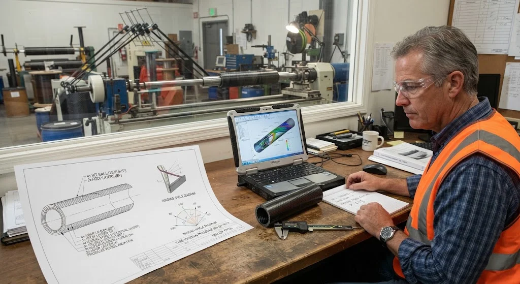
Filament wound epoxy tubes design is the process of translating a load case into a winding program: a choice of fiber, resin, fiber angle, layer sequence, and wall thickness that together produce a tube strong enough for its job and no heavier than necessary. Filament winding is unusually flexible a
Introduction
Filament wound epoxy tubes design is the process of translating a load case into a winding program: a choice of fiber, resin, fiber angle, layer sequence, and wall thickness that together produce a tube strong enough for its job and no heavier than necessary. Filament winding is unusually flexible among composite processes because the fiber angle can be changed continuously along and around the tube, which means the designer can place stiffness and strength exactly where the loads demand it. But that flexibility has a price: the design space is large, and getting it wrong produces tubes that are either overweight or under-strength. This article is a wound tube design guide that walks through the decisions in order — load cases first, then fiber angle, then wall thickness and ply stacking — and explains the verification loop that confirms the design before tooling is cut.
Three parameters dominate filament wound epoxy tubes design: the winding angle sets the direction of the fibers and therefore the directional properties; the wall thickness sets the total load capacity; and the layer sequence determines how the load is distributed between axial and hoop directions. Each interacts with the other two, and all three are constrained by manufacturability — the winding machine, mandrel, and cure cycle.
Filament Wound Epoxy Tubes Design: Starting from the Load Case
Design begins by listing every load the tube will see in service and classifying it by direction. The four fundamental load families for a tube are:
- Axial load: Tension or compression along the tube axis — push rods, struts, drive shafts transmitting thrust, and columns.
- Hoop (circumferential) load: Internal or external pressure acting around the circumference — pressure vessels, pipe, hydraulic cylinders, and vacuum tubes.
- Torsional load: Torque about the tube axis — drive shafts, torsion bars, and coupling tubes.
- Bending load: Moment applied transverse to the axis — beams, cantilever arms, and structural tubes in frames.
Real applications almost always combine two or more of these, and the combination drives the angle selection. The key insight is that a filament wound tube is strongest in the fiber direction, so the winding angle should place fibers along the direction of the largest principal stress. The table below summarizes the angle families used in practice.
| Dominant load | Winding angle | Layer pattern |
|---|---|---|
| Axial tension/compression | 10-30 degrees | Mostly axial layers with light hoop |
| Internal pressure (balanced) | 54.7 degrees (helical) | Alternating ±54.7 helical plus hoop |
| Pure hoop / pressure with high hoop share | 85-90 degrees (hoop) | Hoop layers interleaved with helical |
| Torsion | ±45 degrees | Alternating +45/-45 pairs |
| Bending | 10-30 degrees plus hoop | Axial layers on the outer surface, hoop inside |
The classic pressure-vessel case deserves emphasis: for a closed-end tube under internal pressure, the optimal stress distribution has a 2:1 hoop-to-axial stress ratio, and a ±54.7-degree helical winding produces exactly that balance with minimum wall thickness. This is why the 54-degree angle appears so often in wound pressure equipment.
Wound Tube Design Guide: Fiber Angle and Layer Sequence
Once the load case is classified, the fiber angle is selected, and the layer sequence is built around it. Three rules guide the sequence.
- Alternate angle pairs: Helical layers are wound in balanced pairs, one positive-angle pass followed by one negative-angle pass, so that the tube does not twist or bend under load. A single helical layer would produce a coupled, warping tube; the balanced pair restores symmetry.
- Hoop layers at the surface: Hoop layers (85-90 degrees) are placed on the outer surface for pressure vessels, where they contain the circumferential strain and protect the helical layers. Hoop fibers on the inside diameter are less effective because the stress is lower there.
- Keep the stack thin: Layer count multiplies winding time, and each transition between angle families is a potential source of fiber waviness. For a given wall thickness, fewer, thicker helical layers are usually better than many thin ones.
The sequence matters because adjacent layers of different angles interlace at the crossover points. If hoop layers are wound between helical layers, the surface is more uniform and the helical layers are better supported; if all helical layers are wound first and hoop layers last, the hoop layers sit on a smooth surface but the helical bundle may show gaps. For structural tubes, the interlaced pattern is the default choice.
FW Tube Optimization: Wall Thickness and Ply Stacks
Wall thickness is the last design variable and the one that converts the angle selection into a load capacity. The minimum thickness is set by the governing load case and the allowable stress of the material system, but three practical considerations usually push the design above the pure stress minimum.
- Stability: Thin-walled tubes under compression or bending fail by buckling long before they reach material strength. For a tube under axial compression, the critical buckling load scales with the cube of the wall thickness, so a small thickness increase buys a large stability margin.
- Handling and machining: Walls below about 1.5 mm are fragile during mandrel extraction, machining, and transport. A practical minimum of 1.5-2.0 mm is common for structural tubes regardless of the stress calculation.
- Impact and damage tolerance: A thicker wall tolerates impact damage better — bare-eye-visible damage on a thin tube can reduce compressive strength by half, while a thicker wall contains the damage zone.
The ply stack is then assembled to the required thickness. A typical structural tube might use a stack like: two ±54.7 helical passes, one hoop pass, two more helical passes, and a final hoop pass, where each pass group adds a defined thickness contribution. In practice, wall thickness is built by counting passes rather than plies: the winding program specifies the number of helical passes and hoop passes, and the resulting thickness is verified on a trial tube and adjusted by one pass at a time. This pass-based control is what makes filament wound tubes repeatable in production.
| Design parameter | Typical value range | Design consequence |
|---|---|---|
| Helical angle | 10-55 degrees | Sets axial/hoop strength split |
| Hoop angle | 85-90 degrees | Contains circumferential strain |
| Fiber volume fraction | 60-68% | Raises stiffness; higher risks voids |
| Wall thickness | 1.5-50 mm | Sets load capacity and stability |
| Layer thickness per pass | 0.15-0.6 mm | Determines pass count and winding time |
| Length-to-diameter ratio | up to 50:1 | Limits helical angle range on long tubes |
Composite Tube Engineering: Verification and Iteration
Composite tube engineering does not end at the drawing. Every design assumption — material allowables, fiber volume fraction, cure quality, and the effective angles actually wound — must be verified on hardware before the design is frozen.
- Prototype winding: A first trial tube is wound to confirm that the angle program, mandrel geometry, and cure cycle produce the intended wall thickness and fiber volume fraction.
- Mechanical verification: Coupon and tube-level tests confirm the predicted strengths. Axial tension, hoop tension (NOL ring), and where relevant, burst pressure are compared with the analysis.
- Iteration: If the test results fall short, the angle, the stack, or the material is adjusted — typically one variable at a time — and the cycle repeats until the margin is met.
- Design allowables: For higher-risk applications, the verified properties are reduced by statistically derived knockdown factors (typically A-basis and B-basis allowables) and used as the basis for the production specification.
The iteration loop is cheap at the prototype stage and expensive after tooling, so the design review should be rigorous before the winding program is committed. A structured review checks the load case list, the margin on each load, the manufacturability constraints, and the test plan — in that order.
Frequently Asked Questions
How do I choose the fiber angle for a filament wound epoxy tube?
Classify the dominant load first. Axial loads want low angles (10-30 degrees), internal pressure wants the balanced 54.7-degree helical angle, pure hoop loads want 85-90 degrees, torsion wants ±45 degrees, and bending wants low-angle axial layers with hoop layers for stability. Most tubes carry combined loads, so the angle is chosen to satisfy the highest-stress direction first, then the stack is balanced with additional layers for the secondary direction. If in doubt, start with the ±54.7 balanced helical pattern and add hoop layers until the pressure or stability requirement is met.
What is the minimum wall thickness for a filament wound epoxy tube?
For small structural tubes, a practical minimum of about 1.5-2.0 mm is common, regardless of the stress calculation, because thinner walls are fragile during mandrel extraction, machining, and handling. Larger tubes use thicker walls driven by stability: for compression and bending loads, buckling resistance scales with the cube of the wall thickness, so stability rather than material strength often sets the minimum. The 1.5-50 mm range spans most production tube applications.
How is wall thickness controlled during winding?
Wall thickness is built by counting passes, not plies. The winding program specifies the number of helical passes and hoop passes, and each pass group contributes a known thickness — typically 0.15-0.6 mm per pass depending on fiber count, tension, and resin content. A trial tube is wound, measured, and the pass count is adjusted by one pass at a time until the target thickness is reached. In production, thickness is verified per batch with ultrasonic or dimensional measurement, and the pass count is retained in the batch record.
Can filament wound epoxy tubes be optimized for bending loads?
Yes, but bending is the least efficient load for filament winding, because a tube in bending carries its highest stress at the outer surface and almost none at the neutral axis. The practical design places low-angle axial layers on the outer diameter, where they carry the bending moment, with hoop layers on the inside to stabilize the wall against ovalization and buckling. The wall is thicker than a pure stress calculation suggests because local buckling under compressive bending stress is the governing failure mode for slender tubes.
Conclusion
Filament wound epoxy tubes design is a decision sequence: classify the load, choose the fiber angle, build the layer sequence, set the wall thickness, and verify on hardware. The winding process rewards designers who think in passes and layer pairs, and it punishes designs that ignore stability, handling, and manufacturability. Done systematically, the result is a tube that carries its load at minimum weight with a documented margin — and a winding program that is repeatable in production.
If you are designing a filament wound epoxy tube for your application, explore our filament wound tube range for standard options, or contact our engineering team with your load case, dimensions, and operating conditions — we will help you select the angle, stack, and wall thickness, and qualify the design with prototype winding and testing.
Part of topic
Related Articles
- Fiberglass Filament Wound Tubes: Cost-Effective Alternative to Carbon Fiber
- Filament Wound Epoxy Tubes: Testing Standards and Quality Assurance
- Filament Wound Epoxy Tubes Manufacturing: Process and Quality Control
- Filament Wound Fiberglass Tube: Process Parameters and Performance vs Carbon Fiber
- Pultruded Carbon Fiber Rods: Mechanical Properties and Industrial Applications
- Filament Wound Epoxy Tubes Cost: Materials, Process and Volume Pricing
Interested in Our Products?
Contact our team for competitive pricing and technical specifications.
Get a QuoteRelated Products

Carbon Fiber Fishing Rod Blank
High-quality carbon fiber fishing rod blank manufactured from multiple grades of Toray carbon fiber cloth. Available in a wide range of lengths, powers, and actions for freshwater and saltwater applications. Suitable for OEM rod building.

Carbon Fiber Plate — 3K Twill T700 3.0mm
Medium-thickness 3.0mm carbon fiber plate offering significantly higher load capacity while maintaining attractive 3K twill finish. Suitable for structural brackets, reinforcement plates, and load-bearing panels.

Carbon Fiber Plate — 3K Twill T700 1.5mm
Thin 1.5mm carbon fiber plate with 3K twill weave surface. Lightweight and stiff, commonly used for covers, panels, drone bodies, and applications requiring a premium aesthetic appearance.
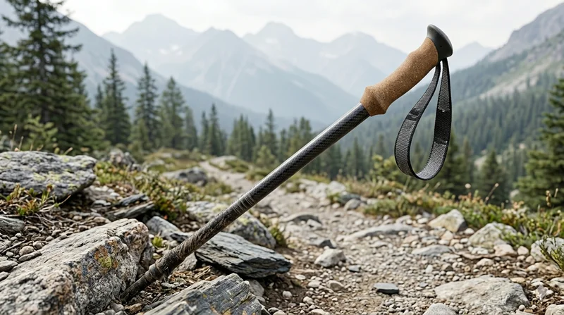
Carbon Fiber Trekking Pole
Lightweight carbon fiber trekking pole manufactured from high-grade carbon fiber tube. Weighs only 160g per pole while providing superior shock absorption and durability for hiking, trail running, and backpacking.

Square Carbon Fiber Tube — 3K Twill T700
Square cross-section carbon fiber tube manufactured with 3K twill weave for torsional strength. Preferred for structural frames, trusses, and support columns where rectangular geometry offers design flexibility.