
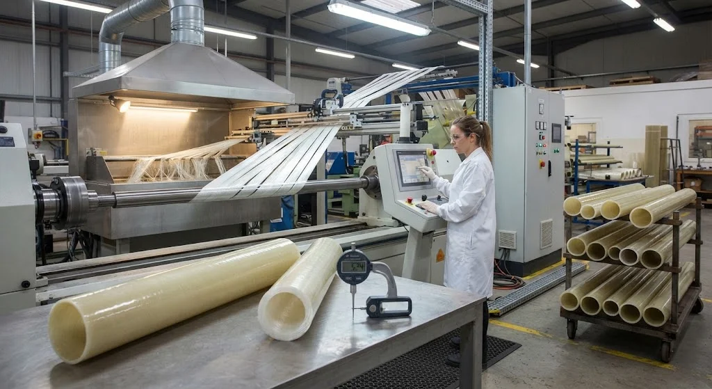
A filament wound fiberglass tube is one of the most widely used structural forms in composite engineering, balancing cost, strength, and corrosion resistance in applications where carbon fiber is unnecessary. The process winds continuous glass fiber rovings, impregnated with epoxy or polyester resin
Introduction
A filament wound fiberglass tube is one of the most widely used structural forms in composite engineering, balancing cost, strength, and corrosion resistance in applications where carbon fiber is unnecessary. The process winds continuous glass fiber rovings, impregnated with epoxy or polyester resin, onto a rotating mandrel at precisely controlled angles. The result is a seamless, hollow tube whose mechanical properties can be tailored by simply changing the winding angle, resin system, and wall thickness. For engineers evaluating tube options, understanding how a filament wound fiberglass tube is made, what parameters control its performance, and how it compares with carbon fiber tube is essential to specifying the right product.
The economics are compelling. Glass fiber costs roughly one-tenth of standard-modulus carbon fiber per kilogram, and filament winding is a fast, automated process that wastes little material. A GFRP wound tube typically delivers 20-40% of carbon fiber stiffness at 15-25% of the material cost, which makes it the rational choice for structural tubes in marine, chemical, electrical, and construction applications. This article details the process parameters that determine quality, quantifies the mechanical performance of glass fiber wound tubes, and provides a structured comparison with filament wound carbon tube.
How Filament Winding Produces Fiberglass Tubes
Filament winding is a continuous, mandrel-based process. Glass fiber rovings are drawn from a creel through a resin bath, then guided by a delivery eye that traverses back and forth along the length of a rotating mandrel. The fibers are laid down at a programmed winding angle relative to the mandrel axis, building up the wall thickness layer by layer. After the required number of passes, the mandrel and tube are cured — either at room temperature for polyester systems or in an oven for epoxy — and the tube is then extracted from the mandrel.
- Helical winding: The delivery eye traverses the full mandrel length while the mandrel rotates, producing fibers at angles of 10-60 degrees to the axis. This is the dominant pattern for structural tubes carrying combined pressure and axial loads.
- Hoop winding: The mandrel rotates rapidly while the delivery eye moves slowly, laying fibers almost perpendicular to the axis (85-90 degrees). Hoop layers maximize burst and internal pressure resistance.
- Polar winding: Fibers pass repeatedly over the mandrel ends, producing near-axial reinforcement for tubes and shafts dominated by bending or axial loading.
Most engineered tubes combine helical and hoop layers in a deliberate stacking sequence. A typical pressure-rated tube might use a 54-degree helical angle — the classic optimum for pressure vessels — with hoop layers added on the outer surface to resist internal pressure, and a protective surface veil to improve abrasion and UV resistance.
Filament Wound Fiberglass Tube: Key Process Parameters
Quality and performance of a filament wound fiberglass tube are governed by a small set of process parameters. The table below summarizes each parameter, its typical range, and the effect it has on the finished tube.
| Parameter | Typical Range | Effect on Performance |
|---|---|---|
| Winding angle (helical) | 10-60 degrees | Determines axial vs hoop strength split; 54 degrees optimizes biaxial pressure loading |
| Fiber volume fraction | 55-70% | Higher fraction raises stiffness and strength; above 70% risks dry fibers and voids |
| Resin content by weight | 25-40% | Lower resin raises mechanicals but reduces corrosion barrier quality |
| Band tension | 10-50 N per roving | Controls fiber straightness and consolidation; low tension causes waviness and voids |
| Mandrel speed | 10-60 rpm | Sets laydown rate; must match traverse speed for correct angle |
| Traverse speed | 0.1-1.0 m/s | Determines bandwidth overlap and surface uniformity |
| Cure temperature | 20-150°C | Full cure is essential for strength; under-cure leaves a soft, weak matrix |
Of these, winding angle and fiber volume fraction dominate the mechanical outcome. A GFRP tube wound at 54 degrees with 60% fiber volume will show axial tensile strength of roughly 300-450 MPa and hoop strength of 150-250 MPa, whereas a near-hoop winding shifts strength almost entirely to the circumferential direction. Specification sheets should always state the winding angle and fiber volume fraction, not just the overall burst rating.
Mechanical Performance of GFRP Wound Tubes
The mechanical properties of a glass fiber wound tube depend on fiber grade (E-glass or the stiffer S-glass/R-glass), resin system, and winding architecture. The table below lists typical values for an epoxy-based E-glass tube wound at 54 degrees with 60% fiber volume fraction.
| Property | GFRP Wound Tube (54°) | CFRP Wound Tube (54°) |
|---|---|---|
| Axial tensile strength (MPa) | 300-450 | 700-1,200 |
| Axial tensile modulus (GPa) | 25-35 | 70-110 |
| Hoop tensile strength (MPa) | 150-250 | 350-600 |
| Density (g/cm³) | 1.9-2.1 | 1.5-1.6 |
| Elongation at break (%) | 2.5-4.0 | 0.8-1.5 |
| Thermal expansion coefficient (10⁻⁶/K) | 6-10 | -0.5 to +0.5 |
| Dielectric strength | Excellent insulator | Conductive |
| Relative material cost per kg | 1x | 8-12x |
Two characteristics deserve emphasis. First, the elongation at break of GFRP is 2.5-4.0%, three to four times that of carbon fiber tube; glass fiber tubes tolerate greater deformation before failure, which improves impact energy absorption and damage tolerance. Second, E-glass is an excellent electrical insulator, whereas carbon fiber is conductive — glass fiber wound pipes are therefore the standard choice for electrical conduit, transformer spacers, and insulator structures where carbon fiber would cause short circuits or galvanic corrosion.
Fiberglass Wound Tube vs Carbon Fiber Tube: How to Choose
Choosing between a fiberglass wound tube and a carbon fiber wound tube is a stiffness-versus-cost trade-off, with weight and electrical properties as secondary factors. The decision framework below covers the common engineering cases.
- Stiffness-critical, weight-neutral structures: If the design is governed by deflection and mass is not critical, carbon fiber's 3-4x higher modulus rarely justifies its 8-12x material cost. A fiberglass wound tube with a larger diameter or thicker wall achieves the required stiffness at lower cost.
- Weight-critical applications: Aerospace, robotics, and high-performance sporting equipment need carbon fiber tube, which offers roughly twice the specific stiffness of glass at one-third less density.
- Corrosion and chemical environments: Both tube types outperform steel, but glass fiber systems are often preferred on cost grounds, with vinyl ester resin for enhanced chemical resistance.
- Electrical applications: Glass fiber is the only choice where electrical insulation or RF transparency is required; carbon fiber conducts and shields.
- Impact and fatigue loading: Glass fiber's higher elongation and strain tolerance give it better impact energy absorption; carbon fiber's fatigue endurance is superior at low strain amplitudes but more sensitive to impact damage.
Glass Fiber Wound Pipe: Applications
Glass fiber wound pipe and tube products serve industries where corrosion resistance, dielectric performance, or cost efficiency matters more than absolute stiffness. Representative applications include:
- Marine and offshore: Shaft liners, masts, stanchions, and seawater cooling piping that resist saltwater attack where steel corrodes and aluminum pits.
- Chemical processing: Ducting, scrubber piping, and tank risers handling aggressive acids and solvents, typically in vinyl ester resin.
- Electrical infrastructure: Transformer spacers, cable conduits, bushing tubes, and insulator cores that exploit glass fiber's dielectric strength and non-conductivity.
- Construction and civil engineering: Lightweight scaffolding components, formwork, and handrails with high strength-to-weight ratio and no maintenance painting.
- Water and wastewater: Large-diameter gravity and pressure pipes for potable water and sewerage, favored for long service life and low friction losses.
- Consumer and sports equipment: Fishing rod blanks, flagpoles, tent poles, and light industrial shafts where cost per unit performance beats carbon fiber.
Frequently Asked Questions
What is the difference between a filament wound fiberglass tube and a pultruded tube?
Filament winding lays resin-wetted glass fibers onto a rotating mandrel at a controlled angle, producing a tube with fibers oriented at an angle to the axis. Pultrusion pulls fibers through a heated die in the axial direction, producing a tube (or solid profile) with fibers predominantly along the axis. Consequently, filament wound tubes are stronger under internal pressure and biaxial loads, while pultruded tubes excel in pure axial stiffness and are cheaper at high volume. For pressure-rated pipes, filament winding is the standard process; for beams and axially loaded struts, pultrusion is often preferred.
How long does a filament wound fiberglass tube last in seawater or chemical service?
With an appropriate resin system — vinyl ester or epoxy with a corrosion barrier layer — filament wound fiberglass tubes are routinely designed for 25-50 year service lives in seawater and chemical environments. The key is preventing moisture or chemical ingress through the resin-rich surface layer; a corrosion barrier of 0.5-1.0 mm of resin-rich material is standard for chemical piping. Unlike steel, glass fiber tube does not suffer galvanic corrosion, and unlike aluminum, it is not susceptible to pitting in chloride environments. Periodic inspection and protection of cut ends and flanges are the main maintenance requirements.
Can a filament wound fiberglass tube replace a carbon fiber tube in my application?
It depends on the governing design constraint. If the application is stiffness-critical at minimum weight — for example a drone arm or a lightweight robot link — carbon fiber's 3-4x higher modulus and 20-30% lower density are difficult to replace; a glass tube of equal stiffness would be noticeably heavier and larger in diameter. If the design is governed by strength, corrosion, cost, or electrical properties, a filament wound fiberglass tube is usually the better economic choice.
Conclusion
A filament wound fiberglass tube provides an optimal balance of cost, corrosion resistance, and structural performance for a broad range of tubular applications. The winding process is precise and tailorable: changing the winding angle, resin system, and layer sequence shifts the mechanical response from axial to hoop strength, letting engineers match the tube to the load case. At roughly one-tenth the fiber cost of carbon and with excellent dielectric and corrosion properties, glass fiber wound tubes are the rational default for marine, chemical, electrical, and construction applications — while carbon fiber tube retains the stiffness-critical, weight-critical tier.
When specifying a fiberglass wound tube, the essential parameters to define are winding angle, fiber volume fraction, resin system, and end finish. Explore our filament wound fiberglass tube range with standard diameters and winding options, or contact our engineering team to discuss custom winding angles, corrosion barrier systems, and prototype quantities.
Part of topic
Related Articles
- Fiberglass Filament Wound Tubes: Cost-Effective Alternative to Carbon Fiber
- Filament Wound Epoxy Tube Design: Wall Thickness, Fiber Angle and Load Optimization
- Filament Wound Epoxy Tubes: Testing Standards and Quality Assurance
- Filament Wound Epoxy Tubes Manufacturing: Process and Quality Control
- Pultruded Carbon Fiber Rods: Mechanical Properties and Industrial Applications
- Filament Wound Epoxy Tubes Cost: Materials, Process and Volume Pricing
Interested in Our Products?
Contact our team for competitive pricing and technical specifications.
Get a QuoteRelated Products

Carbon Fiber Fishing Rod Blank
High-quality carbon fiber fishing rod blank manufactured from multiple grades of Toray carbon fiber cloth. Available in a wide range of lengths, powers, and actions for freshwater and saltwater applications. Suitable for OEM rod building.

Carbon Fiber Plate — 3K Twill T700 3.0mm
Medium-thickness 3.0mm carbon fiber plate offering significantly higher load capacity while maintaining attractive 3K twill finish. Suitable for structural brackets, reinforcement plates, and load-bearing panels.

Carbon Fiber Plate — 3K Twill T700 1.5mm
Thin 1.5mm carbon fiber plate with 3K twill weave surface. Lightweight and stiff, commonly used for covers, panels, drone bodies, and applications requiring a premium aesthetic appearance.
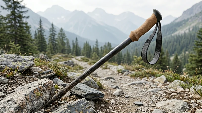
Carbon Fiber Trekking Pole
Lightweight carbon fiber trekking pole manufactured from high-grade carbon fiber tube. Weighs only 160g per pole while providing superior shock absorption and durability for hiking, trail running, and backpacking.

Square Carbon Fiber Tube — 3K Twill T700
Square cross-section carbon fiber tube manufactured with 3K twill weave for torsional strength. Preferred for structural frames, trusses, and support columns where rectangular geometry offers design flexibility.