
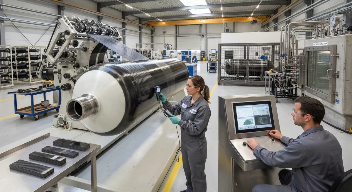
Composite pressure vessels — the fiber-wound tanks that store compressed natural gas, hydrogen, and industrial gases — are among the most safety-critical applications of carbon fiber. A Type IV hydrogen tank operating at 700 bar stores gas at pressures that can drive a crack through a f
Introduction
Composite pressure vessels — the fiber-wound tanks that store compressed natural gas, hydrogen, and industrial gases — are among the most safety-critical applications of carbon fiber. A Type IV hydrogen tank operating at 700 bar stores gas at pressures that can drive a crack through a flawed composite wall in microseconds, which is why the wall thickness design is not an optimization exercise but a safety calculation. The designer must determine how much carbon fiber is needed in the hoop direction and how much in the helical direction, shape the dome so that the fiber paths remain stable under pressure, and apply safety factors that convert theoretical burst pressure into a certification margin acceptable to regulators and customers.
This article walks through the engineering method: the netting analysis that estimates wall thickness from first principles, the stress ratio and winding angle relationships that split material between directions, the dome contour design that keeps fibers in geodesic equilibrium, and the safety factor framework of ISO 11119 and related standards. A worked example shows the calculation from operating pressure to final laminate thickness.
Pressure Vessel Types and Design Standards
Carbon fiber pressure vessels fall into four types defined by their liner and load-sharing arrangement:
- Type III: A metal liner (typically aluminum) that carries a small portion of the pressure load, fully wrapped with carbon fiber composite.
- Type IV: A polymer liner (typically high-density polyethylene or polyamide) that provides the gas barrier but carries no structural load; the composite carries essentially all of the pressure load.
- Type II: A metal liner with hoop-only composite reinforcement — used where weight savings justify the composite without a full wrap.
- Type I: All-metal vessel with no composite; the baseline for comparison.
Design and certification are governed by standards including ISO 11119 (composite gas cylinders), ISO 11439 (CNG containers), and for automotive hydrogen storage, UN GTR No. 13 and SAE J2579. These standards define the minimum burst pressure ratio — the ratio of burst pressure to service pressure — which is the starting point of the thickness calculation. The table below summarizes the key requirements:
| Standard / Application | Min. Burst Ratio (burst/service) | Liner Types Covered | Key Design Input |
|---|---|---|---|
| ISO 11119-2 (Type II, hoop-wrap) | ≥ 2.25 | Metal | Hoop stress in liner + composite |
| ISO 11119-3 (Type III/IV, full wrap) | ≥ 2.25 | Metal / polymer | Composite carries load |
| UN GTR No. 13 (automotive H₂) | ≥ 2.25 (700 bar systems) | Type III/IV | Burst at ambient and extreme temperatures |
| ISO 11439 (CNG on-road) | ≥ 2.25 | Type II/III/IV | Burst at 65 °C, life cycle 11,250+ cycles |
The 2.25 ratio is not arbitrary: it provides margin for fiber strength variability, manufacturing defects, temperature effects, and aging while keeping the vessel light enough to be practical. Designers work backward from this ratio — a 700 bar service vessel must demonstrate burst at or above approximately 1,575 bar — and the wall thickness is sized so that the predicted burst pressure clears this target.
Netting Analysis: The First-Order Thickness Estimate
Netting analysis is the classical first step of wall thickness design. It assumes that only the fibers carry load — the matrix only positions and protects them — which is conservative for design purposes and produces the initial fiber content estimate. For a filament-wound cylinder under internal pressure, the pressure generates two membrane stresses: a hoop (circumferential) stress and an axial stress. For a thin-walled cylinder these are:
- Hoop stress: σ_hoop = P·D / (2·t)
- Axial stress: σ_axial = P·D / (4·t)
where P is pressure, D is the mean diameter, and t is the wall thickness. The hoop stress is exactly twice the axial stress, which dictates the winding architecture: the fibers must be arranged so that the material's capacity is distributed in the same 2:1 ratio. In practice this means a helical layer wound at a winding angle near 90° carries the hoop load, while helical layers wound at a lower angle (typically 10-25°) carry the axial load and tie the cylinder to the dome.
The netting equations solve the thickness of each layer set. For a helical layer at winding angle α, the fiber orientation relative to the cylinder axis is α, and the contribution of that layer to axial and hoop capacity follows from the fiber area projected in each direction. The result is that the helical layer thickness depends on cos²(α), while the hoop layer carries the remainder. The full wrap is typically a stack of helical layers with alternating ±α angles plus a final hoop layer — the combination that satisfies both stress directions with minimum fiber volume.
Stress Ratio and Winding Angle Selection
The stress ratio and the winding angle are linked design variables. The stress ratio r = σ_hoop / σ_axial is 2 for a pure cylinder under internal pressure, but the dome and the boss geometry modify it, and the designer uses this ratio to decide how much fiber goes into hoop layers versus helical layers. The winding angle itself is chosen from three constraints:
- Geodesic stability: The fiber must follow a geodesic path on the mandrel so that it does not slip during winding or under pressure. On a cylinder of radius R ending in a dome with polar boss of radius r0, the geodesic winding angle at the cylinder is given by sin(α) = r0/R — the boss radius sets the minimum cylinder winding angle.
- Stress balance: The helical layers must supply enough axial capacity; the hoop layers must carry the remaining hoop load. The optimum architecture balances both without over- or under-building either direction.
- Manufacturability: High-angle windings are slow to deposit, and very low angles create fiber buildup at the boss; the chosen angle must be practical on the winding machine.
For a typical Type IV hydrogen tank, the helical winding angle on the cylinder is commonly 10-20°, with 90° hoop layers over-wound at the cylinder center. The design iteration is: pick the boss radius, compute the geodesic angle, distribute the thickness between helical and hoop layers via the netting equations, and verify with finite element analysis that the dome-to-cylinder transition does not create stress concentrations that exceed the fiber strength.
Dome Contour Design
The dome is where pressure vessel design gets difficult. The cylinder can be wound at a constant angle, but on the dome the radius changes continuously from the cylinder radius R down to the boss radius r0, and the geodesic condition requires the winding angle to change along the meridian: sin(α(s)) = r0 / r(s). This relationship defines the ideal dome shape — the isotensoid or geodesic-isotensoid dome — in which every fiber carries the same tensile load and the dome surface follows the natural path of the fibers.
The practical consequence is that the dome cannot be shaped arbitrarily; it must be generated from the geodesic equations, or the fibers will slip or wrinkle during winding and the dome will be over- or under-stressed. Designers generate the dome profile by numerical integration of the equilibrium equations, then verify with winding simulation and physical trials. Dome contour errors are a common root cause of premature burst failure, because a non-geodesic dome concentrates stress at the boss and at the cylinder-dome tangent point. The boss itself — the metallic or polymer fitting at the dome apex — must be shaped so that the fibers wrap smoothly over it, and the boss-to-fiber transition is typically the highest-stress region of the entire vessel.
Safety Factors and Certification Testing
Safety factor application converts the design burst pressure into a certified product. The 2.25 burst ratio is applied at the proof-of-design stage: prototype vessels are pressurized to burst, and the measured burst pressure must meet or exceed 2.25 times the service pressure for the design to pass. Certification programs then add qualification testing beyond burst:
- Hydraulic cycling: Vessels are cycled between low and service pressure for 11,250+ cycles (CNG) or more (hydrogen), then burst tested to verify no fatigue degradation.
- Extreme temperature testing: Burst and cycling at -40 °C and +85 °C, where fiber and matrix properties change significantly.
- Impact and damage tolerance: Drop tests, impact tests, and flaw tests confirm that surface damage does not reduce burst pressure below the required margin.
- Permeability testing: For Type IV hydrogen tanks, hydrogen permeation through the liner must stay below regulatory limits over the service life.
- Environmental aging: Exposure to chemicals, humidity, and UV, followed by burst verification, covers long-term degradation.
Each qualification test can be traced back to a design decision: the cycle life depends on the fatigue performance of the fiber and the residual stress state in the laminate, the damage tolerance depends on the thickness distribution and the presence of sacrificial outer layers, and the burst pressure depends directly on the wall thickness calculated in the netting analysis. The safety factor is not a single number applied at the end — it is embedded in every layer of the design and verified by the test program.
Worked Example: 700 Bar Type IV Hydrogen Tank
A typical design target illustrates the method. Consider a Type IV hydrogen tank with a service pressure of 700 bar (70 MPa), a mean cylinder diameter of 400 mm (radius R = 200 mm), a boss radius of 25 mm, and a carbon fiber with a design tensile strength of 2,800 MPa (a conservative working value for the fiber under biaxial loading). The required burst pressure is 700 × 2.25 = 1,575 bar (157.5 MPa). The geodesic winding angle is sin(α) = 25/200 = 0.125, giving α ≈ 7.2° on the cylinder.
From the netting equations, the total laminate thickness needed to hold the hoop stress at burst is on the order of 10-15 mm for this geometry, distributed between helical layers (which provide axial strength and dome connection) and hoop layers (which carry most of the circumferential load). In practice, the laminate is built as alternating ±7.2° helical layers interleaved with 90° hoop layers, with additional helical plies at the dome. The result is a vessel weighing roughly 40-50 kg for a 150-liter tank — about 70% lighter than a comparable all-steel cylinder — which is why carbon fiber is specified despite the material cost. Every parameter in this example — the 2.25 ratio, the boss radius, the fiber strength, the diameter — changes the thickness, and each one is a decision point in the design review.
Frequently Asked Questions
What is the minimum burst pressure ratio for composite pressure vessels?
Most international standards — ISO 11119, ISO 11439, and UN GTR No. 13 for automotive hydrogen — require a minimum burst pressure of 2.25 times the service pressure. A 700 bar hydrogen tank must therefore demonstrate burst at or above roughly 1,575 bar, with additional qualification tests for cycling, temperature extremes, impact, and aging.
What is netting analysis in pressure vessel design?
Netting analysis is a first-order design method that assumes only the fibers carry the pressure load — the matrix merely positions and protects them. It calculates the fiber thickness required in the hoop and helical directions from the membrane stresses of the pressurized cylinder, providing the initial wall thickness estimate that is later refined with finite element analysis and prototype burst testing.
Why does the winding angle depend on the boss radius?
For the fiber to follow a stable geodesic path on the mandrel, the winding angle at the cylinder is related to the boss radius: sin(α) = r0/R, where r0 is the boss radius and R is the cylinder radius. A larger boss forces a larger minimum winding angle, which changes the balance between helical and hoop layers and therefore the wall thickness distribution.
How is the dome shape of a pressure vessel determined?
The dome shape is generated from the geodesic equilibrium equations: because the radius changes continuously from the cylinder to the boss, the winding angle must change along the meridian according to sin(α(s)) = r0/r(s). The resulting isotensoid dome keeps every fiber at equal tension, preventing fiber slippage and stress concentration at the boss.
Conclusion
Composite pressure vessel wall thickness design is a chain of linked calculations: the 2.25 safety ratio sets the burst target, netting analysis distributes the fiber between hoop and helical layers according to the 2:1 stress ratio, the boss radius fixes the geodesic winding angle, and the dome contour follows from the equilibrium of the wound fibers. Every layer — from fiber strength and diameter to the certification test matrix — traces back to the thickness calculation, which is why getting the first-order numbers right is the foundation of a safe, certified, and competitive vessel. For suppliers, this is also the buyer's language: tank manufacturers purchase carbon fiber to meet a thickness and strength target, and understanding the design method is the key to serving them.
YongXian supplies high-performance carbon fiber tow, fabrics, and winding-grade reinforcement materials for pressure vessel programs. Explore our carbon fiber product range or contact our engineering team to discuss material systems for your Type III or Type IV tank program.
Part of topic
Related Articles
- Bio-Based Carbon Fiber Precursors: Lignin and Polyethylene for Low-Cost Production
- Large-Tow Carbon Fiber Cost Analysis: 48K vs 60K Price-Performance Comparison
- Carbon Fiber-Resin Interface Bonding: Surface Treatment and Coupling Agent Optimization
- Digital Twin for Carbon Fiber Manufacturing: Real-Time Process Monitoring and Defect Prevention
- Thermoplastic Carbon Fiber Welding for Automotive: Ultrasonic and Induction Welding Process Windows
- Large-Tow Carbon Fiber Wet Spinning: Process Optimization for 48K/60K Production Efficiency
Interested in Our Products?
Contact our team for competitive pricing and technical specifications.
Get a QuoteRelated Products

Carbon Fiber Plate — 3K Twill T700 3.0mm
Medium-thickness 3.0mm carbon fiber plate offering significantly higher load capacity while maintaining attractive 3K twill finish. Suitable for structural brackets, reinforcement plates, and load-bearing panels.

Carbon Fiber Plate — 3K Twill T700 1.5mm
Thin 1.5mm carbon fiber plate with 3K twill weave surface. Lightweight and stiff, commonly used for covers, panels, drone bodies, and applications requiring a premium aesthetic appearance.

Custom Carbon Fiber Medical Device Components
Medical-grade carbon fiber components manufactured for imaging equipment, surgical instruments, and patient support systems. Carbon fiber's radiolucency (X-ray transparency) and high strength-to-weight ratio make it ideal for CT scanner beds, wheelchair frames, surgical robot arms, and MRI-compatible accessories. Biocompatible resin systems available.

Square Carbon Fiber Tube — 3K Twill T700
Square cross-section carbon fiber tube manufactured with 3K twill weave for torsional strength. Preferred for structural frames, trusses, and support columns where rectangular geometry offers design flexibility.

Carbon Fiber Fishing Rod Blank
High-quality carbon fiber fishing rod blank manufactured from multiple grades of Toray carbon fiber cloth. Available in a wide range of lengths, powers, and actions for freshwater and saltwater applications. Suitable for OEM rod building.