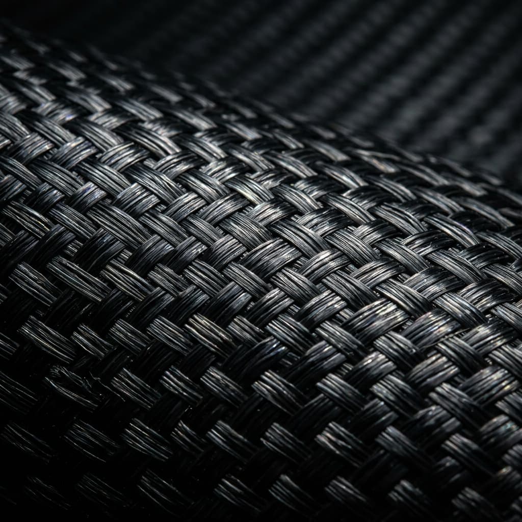
A carbon fiber composite mold maker decides whether your part arrives on the drawing or beside it. Tooling sets the surface, the draft, the split lines and the thermal behavior of every cycle that follows, so a two-tenths error at the plug stage becomes a rejected lot fifty parts later. This guide e
Introduction
A carbon fiber composite mold maker decides whether your part arrives on the drawing or beside it. Tooling sets the surface, the draft, the split lines and the thermal behavior of every cycle that follows, so a two-tenths error at the plug stage becomes a rejected lot fifty parts later. This guide explains which tooling materials fit which programs, what the fabricator actually controls, how a carbon fiber composite mold fabrication runs from first plug to signed-off tool, and the checks to run before you release a deposit.
It also covers lead time, warranty and change-order terms, because the commercial structure of a tooling order shapes the tool as surely as the CNC program does.
Tooling Materials: Epoxy Board, Aluminum, Invar and Carbon Fiber Platens
The material choice follows the part, not the habit of the shop. Cast epoxy tooling board suits low-volume prototyping up to roughly one hundred cycles; it machines fast, holds detail well and repairs easily, but it expands enough that large plaques need a support frame. Machined aluminum tools run thousands of cycles and shed heat quickly, which suits fast epoxy cures but punishes parts with thick sections because the tool pulls heat out of the laminate unevenly. Invar is chosen when the part and the tool must expand at nearly the same rate, typically autoclave prepreg work with tight aerodynamic profiles. Carbon fiber reinforced platens and closeout tools combine stiffness with a matched expansion rate when the tool itself must behave like the part.
| Tooling material | Typical life | CTE behavior | Best fit | Watch-out |
|---|---|---|---|---|
| Cast epoxy board | 50 to 100 cycles | High expansion | Prototypes, geometry sign-off | Needs support frame above 1.5 m |
| Machined aluminum | 2,000 to 10,000 cycles | Medium, high conductivity | RTM and compression production | Fast heat loss in thick laminates |
| Invar 36 | 1,000 plus cycles | Near-zero expansion | Autoclave prepreg, tight profiles | Cost and long machining time |
| Carbon fiber platen | 500 plus cycles | Tunable to the part | Matched tooling, bond fixtures | Requires controlled layup and cure |
| Nickel electroform shell | Thousands of cycles | Set by the backing | High-gloss class-A surfaces | Repair limited, long build time |
Ask for the expansion calculation in writing: the fabricator should state the tool CTE, the part laminate CTE and the expected dimensional drift across the full cure range. A supplier who cannot show that number is guessing with your tolerance.
What a Carbon Fiber Composite Mold Maker Controls
Four control points separate a controlled tool from an expensive fixture. Each one should appear in the quotation as a measurable deliverable, not a marketing phrase.
- Plug accuracy: the master plug is cut from a single interpolated tool path and verified with a CMM report against the CAD nominal, including surface deviation maps rather than five point readings.
- Surface class: the agreed finish grade (tooling gelcoat to a Class A polish, or a matte tooling surface for bonding) written into the purchase order with the measurement method used to accept it.
- Thermal design: heater placement, thermocouple map and exotherm management for thick sections, so the tool heats the part rather than the other way around.
- Seal and vent layout: vacuum channel geometry, seal groove depth and vent positions defined before the first cut, because reworking a seal groove after cure shortens tool life immediately.
A carbon fiber composite mold maker who owns these four items can repeat the tool across cavities. One who outsources the plug and copies the seal layout from a previous job cannot.
Carbon Fiber Composite Mold Fabrication: From Plug to Matched Tool
Every serious fabrication follows the same spine. The sequence below is what a qualified shop should walk you through before contract award.
- Step 1, engineering review: draft angles, split line, shrink compensation and ejector strategy confirmed against the part drawing, with a written list of open questions returned to your engineers.
- Step 2, plug build: CNC-machined board or printed mandril, bonded, filled, sealed and hand-finished, then scanned for deviation against CAD.
- Step 3, mold construction: tooling gelcoat, structural layup over the plug, cure, separation, flange and stiffener installation, then finish machining of registration pins and clamp surfaces.
- Step 4, validation: first-article inspection on the tool itself, a trial ply or trial shot, dimensional report, and a signed bounce-back that lists what changed and why.
Insist on the deviation report from step two before you approve step three. It is the cheapest moment to catch a plug error, and the most expensive to correct after the mold is cured.
Carbon Fiber Composite Mold Maker US: Qualification Checklist
Distance matters in tooling: visiting the shop, watching a layup and arguing about a split line in person beats any video call. Run these checks against any candidate, domestic or overseas.
- CMM and scan capability in house: ask who runs the report, and see a sample with surface deviation color maps attached.
- Material traceability: lot numbers for gelcoat, core and structural laminates, with certificates filed against your tool number.
- Process documentation: cure charts with actual measured temperatures, not only controller setpoints, plus the vacuum log for the layup.
- Warranty terms in writing: cycle count or time period, what voids coverage, and how a cracked gelcoat surface is repaired during warranty.
- Change control: a signed change order path for any deviation from the released tool drawing, so cost and schedule moves are never silent.
Two references from programs of similar size tell you more than a capability list. Call them, and ask what broke during that tooling program.
Tooling Cost, Lead Time and Commercial Terms
Tooling quotations vary widely because the scope hides in the details. Fix the scope first, then compare numbers.
| Scope item | What belongs in the quote | Typical lead time |
|---|---|---|
| Prototype tool | Plug, single-face mold, no production flange | 3 to 5 weeks |
| Production matched tool | Core and cavity, flanges, registers, seal system | 7 to 12 weeks |
| Tryout and correction | Trial ply, dimensional report, one correction round | 1 to 2 weeks after delivery |
| Spare inserts and seals | Wear parts listed with per-unit pricing | Quoted separately |
| Engineering changes | Signed change order with cost and schedule impact | Assessed per request |
Payment normally runs in milestones: deposit at order, payment at plug approval, balance at delivery against the dimensional report. Retain a holdback until the trial ply passes. Incoterms, packaging for sea freight and insurance belong on the purchase order, and so does the ownership clause for the plug and the CAD files used to cut it.
Frequently Asked Questions
Who owns the plug and the tooling CAD files?
You should. Write into the contract that the plug, the tool drawings and the machining programs are your property, delivered on request at any milestone. Shops sometimes claim the programs as their process knowledge; settle this before the deposit, because negotiating it after a dispute leaves you with little leverage.
How many cycles should a production mold guarantee?
Epoxy board tools are typically quoted at 50 to 100 cycles, aluminum in the low thousands, Invar and carbon tooling well beyond that when maintained. The guarantee must name the maintenance regime too: cleaning, seal replacement and storage conditions all affect the number, and a warranty without those conditions is hard to enforce.
Can the same maker handle both the mold and the first production parts?
Often yes, and it shortens the loop between a dimensional miss and its correction. Check that the production side has its own process control: a shop that excels at tooling does not automatically run a qualified layup and cure line. Ask for the production certification separately from the tooling references.
Conclusion
A carbon fiber composite mold maker earns the order by showing the expansion calculation, the deviation report from the plug, the measured cure charts and the warranty in writing. Match the tooling material to the cycle count and tolerance, hold a payment milestone until the trial ply passes, and keep every document with the tool number for the life of the program.
YongXian builds carbon fiber composite tooling and production parts for OEM programs, with lot-traceable materials, measured cure records and export documentation. Browse our composite products or send your part drawing, cycle count and target tolerance for a tooling quotation.
Part of topic
Related Articles
- Carbon Fiber Composite Hardener Supplier: Curing Agents for Epoxy Systems
- Carbon Fiber Composite Resin Mill: A Buyer Qualification Guide
- Carbon Fiber Composite Resin Manufacturer: Capacity, Chemistry and Scale-Up
- Carbon Fiber Composite Resin Supplier: Epoxy, Hardeners and Supply Terms
- Carbon Fiber Sheets in South Africa: Import and Stock Guide
- How Much Is Carbon Fiber Fabric: Price per Square Meter
Interested in Our Products?
Contact our team for competitive pricing and technical specifications.
Get a QuoteRelated Products

Custom Carbon Fiber Bicycle Frame
Full-custom carbon fiber bicycle frame manufactured to your geometry specifications. We produce road, gravel, mountain, and track frames using high-modulus carbon fiber layups optimized for each riding discipline. Monocoque construction with internal cable routing, available with disc or rim brake mounts.
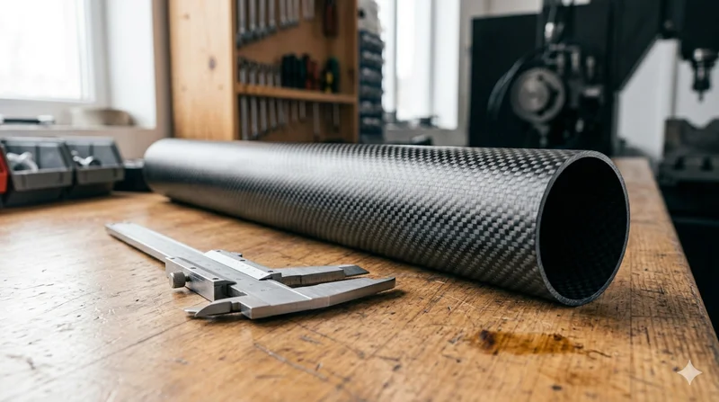
Round Carbon Fiber Tube — 3K Plain Weave T700
Standard round carbon fiber tube manufactured from Toray T700 grade fiber with 3K plain weave. Offers balanced strength and stiffness for general industrial applications including robotics, automation, sports equipment, and aerospace structures.
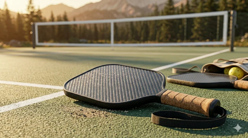
Carbon Fiber Pickleball Paddle
High-performance pickleball paddle with Toray T700 carbon fiber face and polypropylene honeycomb core. Delivers excellent power-to-weight ratio, spin generation, and vibration dampening for competitive play.
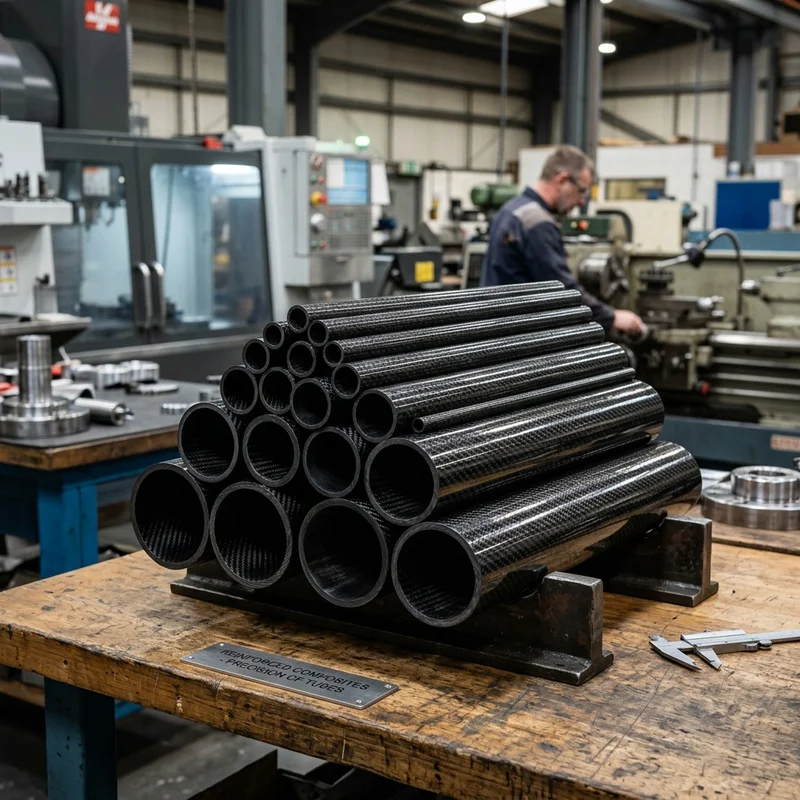
Round Carbon Fiber Tube — 3K Twill
Lightweight and ultra-stiff round tubes ideal for drone frames, robotics, and structural applications.
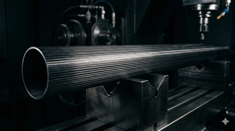
Round Carbon Fiber Tube — UD Unidirectional T700
Unidirectional (UD) round tube with all fibers aligned axially for maximum longitudinal stiffness. Ideal for applications requiring high bending rigidity with minimal weight, such as shafts, struts, and structural reinforcements.