
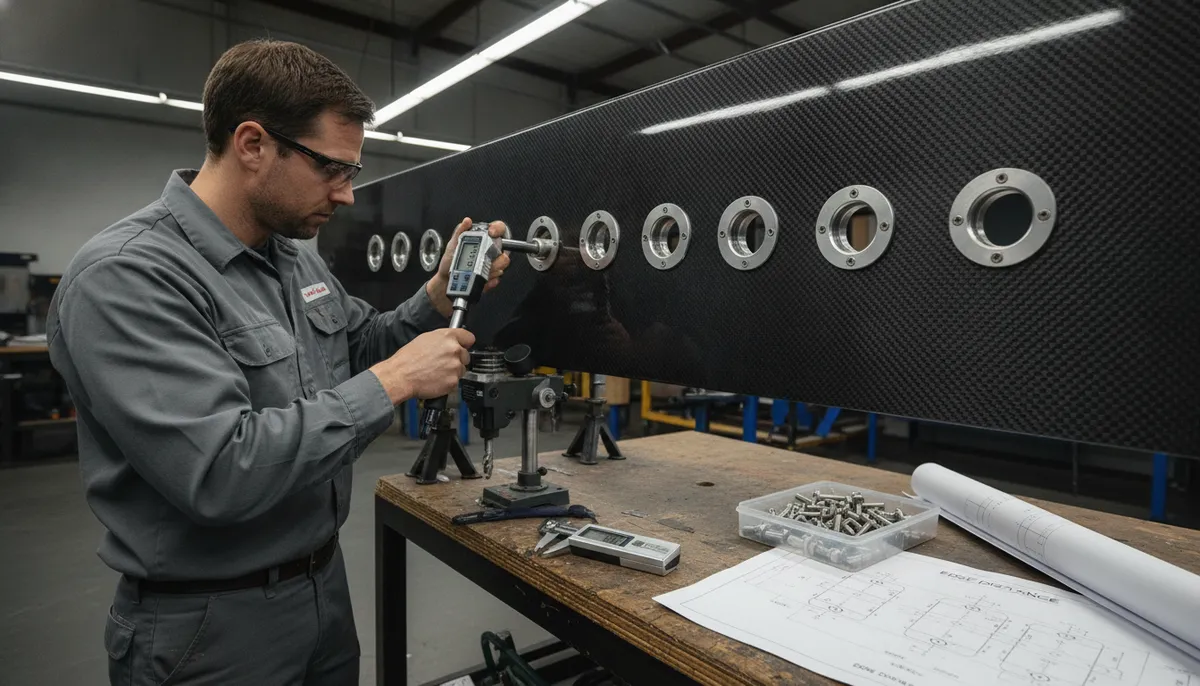
Carbon fiber reinforced polymer (CFRP) structures rarely end their lives as single cured components. Frames meet skins, spars meet ribs, and subassemblies must be attached in the field or removed for maintenance. For these demountable connections, bolted joints remain the dominant solut
Introduction
Carbon fiber reinforced polymer (CFRP) structures rarely end their lives as single cured components. Frames meet skins, spars meet ribs, and subassemblies must be attached in the field or removed for maintenance. For these demountable connections, bolted joints remain the dominant solution: they tolerate assembly tolerances, allow disassembly, and transfer load reliably when designed correctly. The difficulty is that composites respond to bolt loading very differently from metal.
Unlike steel or aluminum, CFRP has no plastic redistribution zone around a fastener hole. Load concentrates at the hole edge, and failure occurs through bearing, net tension, shear-out, or cleavage almost without warning. Three decisions control whether a bolted carbon fiber joint performs well: the bearing strength available from the laminate, the quality of the drilled hole, and the stack-up configuration that distributes load between the bolt and the laminates. This article walks through each of these in the order they influence a real design.
Why Bolted Joints Dominate Composite Assembly
Adhesive bonding offers higher static strength, but bolting is chosen wherever the structure must be separated. The practical drivers are consistent across industries:
- Disassembly and maintenance: inspection intervals, repair access, and component replacement all require joints that can be opened without destroying the laminate.
- Assembly tolerance management: bonded joints demand tightly controlled bond gaps and surface preparation, while bolted joints absorb dimensional variation between large parts.
- Load reversal and fatigue: peel stresses can debond an adhesive joint under repeated loading, whereas mechanically fastened joints transfer shear through the bolt shank with predictable fatigue behavior.
- Hybrid material attachment: CFRP-to-metal and CFRP-to-wood connections are far simpler to engineer with bolts than with adhesives because thermal expansion mismatch does not load the joint interface.
The consequence is that nearly every production carbon fiber structure — from aircraft fuselage sections to wind blade roots to industrial robot arms — contains hundreds or thousands of bolted connections, and their efficiency directly sets the weight and cost of the assembly.
Bearing Strength and Joint Efficiency
Bearing strength is the pressure capacity of the laminate at the hole edge in the direction of the applied load, expressed as load divided by hole diameter and laminate thickness. Typical bearing strength values for aerospace-grade CFRP laminates are shown below alongside the mechanical properties that govern each failure mode:
| Property | Quasi-isotropic CFRP Laminate | Steel (A286 Bolt Reference) | Design Consequence |
|---|---|---|---|
| Bearing strength (E/D ≥ 4) | 450-700 MPa | Yield 600-850 MPa | Bearing usually governs at low edge-distance |
| Ultimate bearing strain | 1.5-2.5% | 12-18% | Composites fail with little plastic warning |
| Net-tension strength | 60-75% of unnotched tensile | Not applicable | Minimized by widening the ligament |
| Shear-out strength | 50-80 MPa | Allowable ~200 MPa | Minimized by raising edge distance |
| Density | 1.55-1.60 g/cm³ | 7.9 g/cm³ | Joint weight dominated by fitting and bolt mass |
Joint efficiency — the ratio of bolted joint strength to the strength of an unholed laminate — typically reaches 55-65 percent for an optimized single-row double-lap joint in quasi-isotropic CFRP. Designers push efficiency upward with three geometric levers: increasing edge distance to at least 3-4 hole diameters, enlarging hole pitch to 4-5 diameters, and choosing a double-lap configuration that eliminates the bending eccentricity of single-lap joints. At the system level, a 10 percent gain in joint efficiency translates directly into 10 percent less laminate area at every attachment point.
Hole Quality and Tolerance: The Drilling Problem
Because composite bearing strength depends on intact fibers at the hole wall, hole quality is the single most process-sensitive factor in bolted joint design. Drilling that tears fibers, generates heat above the resin glass transition, or pushes uncut plies out of the back face reduces bearing strength by 10-30 percent even when the hole appears visually acceptable. The manufacturing rules that protect hole quality are specific:
- Diamond or carbide tooling with positive rake: standard twist drills designed for metal tear the exit plies; PCD-tipped or burr-style carbide drills with controlled feed produce clean edges.
- Peck drilling or backing support: a sacrificial backer plate or climb-milling strategy prevents exit-side delamination, which is otherwise the dominant drilling defect.
- Feed and speed windows: feed rates below roughly 0.05 mm/rev with spindle speeds of 6,000-12,000 rpm minimize heat and delamination in typical aerospace CFRP; the specific window is laminate-dependent.
- Hole tolerance control: close-fit holes (H7, roughly +0.02/+0.03 mm on typical fastener diameters) maximize bearing contact but complicate assembly; clearance-fit holes (up to +0.5 mm) ease installation at the cost of up to 20-30 percent lower static bearing efficiency.
After drilling, borescope or threshold ultrasonic inspection of every third hole is common where certification allows, and countersinking must be checked for fiber breakout at the countersunk edge. A clean hole with a tolerance of +0.1 mm over nominal typically delivers 90-100 percent of the laminate's intrinsic bearing strength; a damaged hole with visible exit delamination may deliver only 70-80 percent.
Stack-Up Configurations and Failure Modes
The stack-up — how multiple laminates and washers are arranged around the bolt — decides the failure mode and the efficiency of the joint. The table below compares the standard configurations used in CFRP assembly:
| Configuration | Typical Bearing Efficiency | Failure Mode | Primary Use |
|---|---|---|---|
| Double-lap (two outer laminates, one inner) | 90-100% | Bearing in the thinnest laminate | Primary structure, aircraft spars and ribs |
| Single-lap (two laminates overlapped) | 40-55% | Secondary bending, bearing + net tension | Skinned panels, brackets, repairs |
| Single-lap with two bolts in row | 55-70% | Bearing at the loaded edge bolt | Higher loaded panels with space for pitch |
| Countersunk (flush) bolted double-lap | 80-95% | Bearing with reduced section at countersink | Aerodynamic surfaces requiring flush finish |
Single-lap joints fail at roughly half the efficiency of double-lap because the load path is eccentric: the bending induced at the overlapping edge creates secondary stresses that reduce bearing capacity and can initiate delamination at the bolt row. Wherever double-lap geometry is possible — by adding a third laminate, an angled fitting, or a built-up lug — the efficiency gain of 35-50 percentage points usually justifies the added part count. When single-lap is unavoidable, designers compensate with larger edge distances, thicker laminates at the bolt row, or two fasteners in series rather than one.
Fastener Selection and Installation Practice
The fastener itself and the way it is installed complete the joint design. Titanium and corrosion-resistant steel bolts are standard in aerospace CFRP because they avoid the galvanic corrosion that unprotected aluminum fasteners cause against the carbon cathode. Three installation details matter most:
- Washers under head and nut: a hardened washer of at least 0.8-1.0 times the bolt diameter distributes clamping load and prevents the fastener head from crushing the outer plies; this is not optional on CFRP.
- Torque control: clamping pressure adds through-thickness compression that raises bearing capacity, but overtightening distorts the hole and damages the laminate. Verified torque values, re-torque checks after initial seating, and torque-stripe marking are standard practice.
- Hole preparation for interference bolts: where fatigue governs, interference-fit fasteners cold-expand the hole slightly and leave residual compression at the hole edge; the resulting fatigue life gain of 3-10x must be balanced against the increased insertion damage risk during installation.
For bolted CF-containing assemblies in corrosive services, sealants or wet installation with a qualified primer are specified at the faying surfaces to block galvanic couples. Every fastener, hole, and stack-up combination used in a certified design should be validated by joint-level test coupons rather than extrapolated from laminate data alone.
Frequently Asked Questions
Why do bolted composite joints fail at much lower efficiency than bolted metal joints?
Metal joints redistribute load plastically around the hole, so the load spreads across the ligament before ultimate failure. Carbon fiber composites are elastic to rupture: stress concentrates at the hole edge and local fiber failure propagates without redistribution, so the usable strength is governed by the bearing limit at that edge. In addition, composites are sensitive to hole quality, edge distance, and eccentricity in a way that ductile metals are not. When all geometric and process factors are optimized, a well-designed bolted CFRP joint can still reach 55-65 percent efficiency for single-row double-lap joints, which is sufficient for most primary structures but is fundamentally lower than the 90-100 percent typical of ductile metal joints.
What is the minimum edge distance and hole pitch for carbon fiber bolted joints?
Industry practice for loaded CFRP bolted joints is an edge distance of at least 3-4 hole diameters in the load direction and a hole pitch of 4-5 diameters in the load row. Below roughly 3 diameters edge distance, shear-out can dominate and bearing strength drops sharply; below 4 diameters pitch, adjacent hole interactions reduce net-tension margins. For unloaded edges, 2-2.5 diameters is generally accepted. These ratios apply to bolted joints in standard quasi-isotropic laminates; highly orthotropic layups, such as unidirectional spar laminates in wind blades, require larger edge distances in the weak direction because shear-out resistance is lower.
Should I use bolts or adhesive bonding for joining carbon fiber parts?
The choice depends on whether the joint must be disassembled. Adhesive bonding gives higher static strength, a continuous load path, and no stress concentration at hole edges, but it cannot be opened for inspection or replacement and is sensitive to surface preparation and peel loads. Bolted joints provide demountability, tolerance absorption, and predictable fatigue, at the cost of lower efficiency and weight added by the fasteners. Hybrid approaches — a bonded joint with bolts as fail-safes — are common in aircraft primary structure and wind blade roots, where certification requires mechanical backup even when the bond carries the load. For most B2B structural applications, if the assembly will ever be serviced or overhauled, bolting is the pragmatic default.
Conclusion
Bolted joint design determines whether a carbon fiber structure can be assembled, maintained, and trusted in service. Bearing strength sets the size of the connection, hole quality and tolerance set how much of that strength survives drilling, and stack-up configuration sets whether the joint reaches 40 or 100 percent of its theoretical efficiency. Mastering these three levers — together with proper washer, torque, and galvanic protection practice — is what separates a carbon fiber assembly line that works from one that suffers field failures at the bolt rows.
For engineers building demountable carbon fiber structures, the practical path is to lock the hole-making process early, validate bearing allowables with joint coupons, and prefer double-lap layouts wherever geometry allows. Explore our carbon fiber sheet, fabric, and laminated panel range designed for machined and drilled joints, or contact our engineering team for joint design support, drilling parameters, and material qualification for your application.
Part of topic
Related Articles
- Filament Wound Epoxy Tubes Advantages: Over Metal and Pultruded Alternatives
- Carbon Fiber Tube Strength: Analysis Methods and Design Allowables
- Filament Wound Epoxy Tubes: Mechanical Properties and Material Data Sheets
- Carbon Fiber Drone Blades and Propellers: Stiffness, Balance and Noise Reduction
- Fiberglass Filament Wound Tubes: Cost-Effective Alternative to Carbon Fiber
- Filament Wound Epoxy Tube Design: Wall Thickness, Fiber Angle and Load Optimization
Interested in Our Products?
Contact our team for competitive pricing and technical specifications.
Get a QuoteRelated Products

Carbon Fiber Fishing Rod Blank
High-quality carbon fiber fishing rod blank manufactured from multiple grades of Toray carbon fiber cloth. Available in a wide range of lengths, powers, and actions for freshwater and saltwater applications. Suitable for OEM rod building.

Carbon Fiber Plate — 3K Twill T700 1.5mm
Thin 1.5mm carbon fiber plate with 3K twill weave surface. Lightweight and stiff, commonly used for covers, panels, drone bodies, and applications requiring a premium aesthetic appearance.

Carbon Fiber Plate — 3K Twill T700 3.0mm
Medium-thickness 3.0mm carbon fiber plate offering significantly higher load capacity while maintaining attractive 3K twill finish. Suitable for structural brackets, reinforcement plates, and load-bearing panels.

Custom Carbon Fiber Medical Device Components
Medical-grade carbon fiber components manufactured for imaging equipment, surgical instruments, and patient support systems. Carbon fiber's radiolucency (X-ray transparency) and high strength-to-weight ratio make it ideal for CT scanner beds, wheelchair frames, surgical robot arms, and MRI-compatible accessories. Biocompatible resin systems available.

Square Carbon Fiber Tube — 3K Twill T700
Square cross-section carbon fiber tube manufactured with 3K twill weave for torsional strength. Preferred for structural frames, trusses, and support columns where rectangular geometry offers design flexibility.