
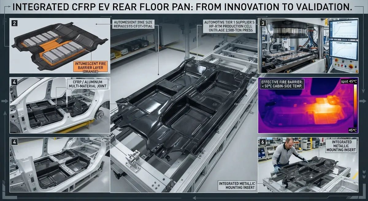
Explore the design and manufacturing of carbon fiber rear floor pans with integrated battery trays for electric vehicles. This structural battery integration approach reduces weight, increases rigidity, and improves crash safety while simplifying assembly.
The Structural Battery Integration Paradigm
Electric vehicle (EV) manufacturers are increasingly adopting structural battery integration — using the battery enclosure as a load-bearing element of the vehicle body rather than a separate, non-structural box bolted to the floor. This paradigm shift has driven interest in carbon fiber composite rear floor pans that combine the floor structure, battery tray, and cross-members into a single integrated component.
By consolidating what was previously 30–50 separate stamped steel or aluminum parts into one carbon fiber structure, automakers can reduce part count, eliminate thousands of spot welds, and achieve significant mass reduction while improving torsional rigidity. The rear floor pan — which forms the floor of the passenger cabin in the rear seat area and supports the battery pack underneath — is the ideal candidate for this integration.
Design Architecture
The integrated carbon fiber rear floor pan serves four structural functions simultaneously:
- Floor panel: Forms the cabin floor in the rear passenger area, supporting occupant loads and providing acoustic and thermal insulation.
- Battery enclosure tray: The underside of the pan incorporates a deep-drawn cavity that houses the HV battery modules. This eliminates the need for a separate battery box, saving 15–25 kg.
- Side sill integration: The lateral edges of the pan merge into the rocker panel structure, transferring side-impact loads into the battery area through controlled crush zones.
- Tunnel reinforcement: A central tunnel section (for rear-wheel-drive architectures housing the drive unit) is integrated as a structural spine, providing longitudinal stiffness.
| Parameter | Steel (Stamped/Welded Assembly) | Aluminum (Cast + Stampings) | CFRP (Integrated Molding) |
|---|---|---|---|
| Total Mass (kg) | 38.5 | 22.0 | 11.5 |
| Part Count | 42 | 18 | 1 (molded + inserts) |
| Spot Welds / Fasteners | 186 | 84 | 6 (adhesive bond + inserts) |
| Torsional Stiffness Contribution (kN·m/°) | 8.2 | 9.5 | 14.8 |
| Crash Energy Absorption (kJ, front offset) | 4.5 | 5.2 | 6.8 |
| Waterproof Rating | IP67 (with sealant) | IP67 (with sealant) | IP68 (inherent) |
| Tooling Cost ($M) | $4.2 | $3.8 | $2.5 |
| Cycle Time per Part | N/A (42 parts) | N/A (18 parts) | 12 min (HP-RTM) |
Manufacturing Process: High-Pressure Resin Transfer Molding
The integrated rear floor pan is manufactured using High-Pressure Resin Transfer Molding (HP-RTM), a process that combines the design freedom of composites with automotive cycle time requirements:
- Preforming: Multi-axial carbon fiber non-crimp fabrics (NCF) are cut and stacked in a preforming station. Localized reinforcements — 12K biaxial NCF in the battery cavity floor, ±45° triaxial fabric in the side sill areas — are strategically placed based on FEA-optimized laminate stacking sequences. The preform is bonded with a spray binder and formed in a heated press.
- Insert placement: Metallic inserts (steel or aluminum) for seat rail attachments, battery module mounting points, and suspension component pickups are loaded into the mold cavity. These inserts are encapsulated during resin injection, eliminating post-mold drilling and assembly operations.
- Resin injection: The closed mold is heated to 120°C, and a fast-curing epoxy resin system is injected at 60–120 bar pressure. The cycle time — from injection to demolding — is 8–12 minutes, compatible with automotive production volumes of 15,000–30,000 parts per year per mold set.
- Post-processing: Flash removal is minimal due to the precision mold gap. The part is post-cured at 180°C for 90 minutes (in-line oven). CNC drilling of 8–12 locating holes and inspection via white-light scanning complete the manufacturing cycle.
Thermal Management and Fire Safety
A critical requirement for any battery tray is thermal management and fire containment. The carbon fiber integrated floor pan addresses this through a multi-layer design:
- Intumescent coating: The battery-facing surface is coated with a 1.5–2.0 mm intumescent fire barrier layer. Under thermal runaway conditions (>250°C), the coating expands to 30–50× its original thickness, forming a ceramic-like char that blocks flame propagation and heat transfer for >15 minutes — exceeding the UN ECE R100 and GB 38031 regulatory requirements.
- Thermal isolation layer: A 3 mm aerogel-infused glass fiber mat is bonded to the cabin-side surface, maintaining the floor temperature below 45°C during normal battery operation and below 70°C during fast charging.
- Integrated cooling channels: The mold design incorporates removable cores that create cooling channels (15–20 mm diameter) within the structure during molding. Coolant flows directly through the composite floor, eliminating separate cooling plates and reducing thermal resistance.
Automotive Applications and OEM Adoption
Multiple OEMs are in various stages of implementing carbon fiber integrated rear floor pans:
- Tesla (Cybertruck, 2025+): Uses a carbon fiber composite rear underbody that integrates the battery enclosure with the rear floor. The single-piece molding replaces 78 stamped steel parts.
- BMW (Neue Klasse platform, 2025+): The rear floor module of certain Neue Klasse EV variants uses a CFRP floor pan bonded to aluminum space frame members. BMW's Landshut plant invested €85 million in HP-RTM capacity for this component.
- Chinese OEMs (NIO, BYD, 2026+): Several Chinese EV manufacturers have developed carbon fiber floor pans for their flagship models. NIO's ET9 sedan uses a CFRP rear floor tray manufactured by HP-RTM that integrates the battery fire barrier as a co-cured layer, reducing assembly time by 40% compared to the previous generation steel + separate fire shield design.
Frequently Asked Questions
How does a carbon fiber battery tray handle thermal runaway from lithium-ion cells?
The integrated floor pan uses a three-layer fire safety system: (1) an intumescent coating on the battery-facing side that expands under heat to form an insulating char barrier, (2) an aerogel-infused glass fiber mat on the cabin side for thermal isolation, and (3) the carbon fiber laminate itself, which chars but does not melt or drip when exposed to flame. In UN ECE R100 testing, CFRP battery enclosures have demonstrated >15 minutes of fire resistance — meeting the 5-minute minimum requirement with a 3× safety margin. The carbon fiber material itself is inherently non-flammable (limiting oxygen index >45%), providing additional safety compared to aluminum, which can melt and collapse at 660°C.
What is the cost comparison between CFRP and aluminum battery trays?
At current production volumes (10,000–30,000 units/year), the per-unit cost of a CFRP integrated floor pan is approximately $420–$580, compared to $280–$380 for a multi-part aluminum assembly and $180–$250 for a steel assembly. However, the CFRP solution provides system-level savings: (1) 15–25 kg weight reduction, (2) elimination of 36 separate parts and 180 spot welds, (3) 40–50% reduction in assembly labor, and (4) simplified sealing and corrosion protection (no galvanic corrosion concerns). When these system savings are included in a total cost of ownership analysis, CFRP becomes cost-competitive with aluminum at production volumes below 50,000 units/year and with steel below 100,000 units/year. For low-volume premium EVs (5,000–15,000 units/year), CFRP is the most cost-effective solution today.
Can the carbon fiber floor pan be repaired after a crash?
Repair of CFRP floor pans is possible but requires specialized procedures. Minor cosmetic damage (surface scratches, gelcoat chips) can be repaired using standard composite repair protocols — grind, clean, apply patch prepreg, and cure. Structural damage to the battery tray area requires evaluation by the OEM's certified repair network. Many manufacturers design the floor pan with a replaceable impact-absorbing subframe that bolts to the main CFRP structure, creating a sacrificial zone that can be replaced without composite repair. For damage to the molded CFRP structure itself, OEM-approved repair methods include: (1) bonded composite patch repairs (for cracks and delamination up to 100mm), and (2) full replacement of the floor pan (bolted to the body structure at 24 attachment points). Carbon fiber's high specific energy absorption means that in many moderate-speed collisions, the CFRP pan survives without damage while the surrounding metal structure deforms — a characteristic not possible with metal-only designs.
Part of topic
Related Articles
- Carbon Fiber Mooring for Floating Offshore Wind: Fatigue and Corrosion in Deep Water
- Carbon Fiber Bicycle Frame Optimization: Layup Design and Manufacturing for Competitive Racing
- Carbon Fiber CFRP Retrofit for Infrastructure: Bridge and Building Seismic Strengthening
- Carbon Fiber Medical Imaging Equipment: Lightweight Gantry and Couch Structures for MRI/CT
- Carbon Fiber EV Battery Enclosures: Crash Safety and Electromagnetic Shielding Design
- Carbon Fiber Structures for Low-Altitude Economy: UAV Airframes and eVTOL Components
Interested in Our Products?
Contact our team for competitive pricing and technical specifications.
Get a QuoteRelated Products

Carbon fiber standard plate-3k stripe
Lightweight, ultra-rigid standard sheets for drone fuselages, robot housings, facades and structural applications.

Carbon Fiber Plate — 3K Twill T700 3.0mm
Medium-thickness 3.0mm carbon fiber plate offering significantly higher load capacity while maintaining attractive 3K twill finish. Suitable for structural brackets, reinforcement plates, and load-bearing panels.

Carbon Fiber Plate — 3K Twill T700 1.5mm
Thin 1.5mm carbon fiber plate with 3K twill weave surface. Lightweight and stiff, commonly used for covers, panels, drone bodies, and applications requiring a premium aesthetic appearance.

Square Carbon Fiber Tube — 3K Twill T700
Square cross-section carbon fiber tube manufactured with 3K twill weave for torsional strength. Preferred for structural frames, trusses, and support columns where rectangular geometry offers design flexibility.

Carbon Fiber Plate — UD Unidirectional T700
Unidirectional carbon fiber plate with all fibers oriented in a single direction for maximum strength along the fiber axis. Essential for structural reinforcements, splints, and applications where load direction is predictable.