
The wing skin is the largest single structural component of a modern airliner's airframe, and on current-generation programs it is also the most visible demonstration of carbon fiber's structural capability. On the Airbus A350 XWB and the Airbus A220, upper and lower wing skins are manu
Introduction
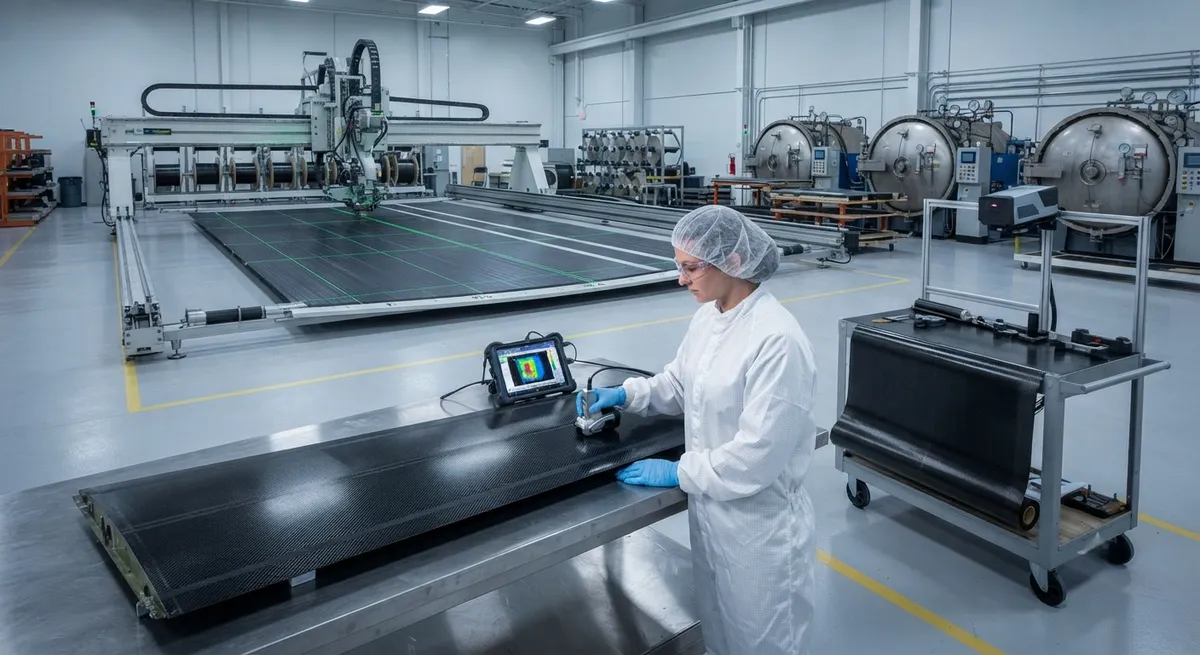
The wing skin is the largest single structural component of a modern airliner's airframe, and on current-generation programs it is also the most visible demonstration of carbon fiber's structural capability. On the Airbus A350 XWB and the Airbus A220, upper and lower wing skins are manufactured as large single-piece carbon fiber reinforced polymer (CFRP) panels. A single upper wing skin panel can exceed 30 meters in length and 4 meters in width, carrying the dominant share of wing bending loads while the stringers, spars, and ribs complete the load path. Producing these panels as one continuous part eliminates thousands of fasteners and the heavy metal splice plates that aluminum wing construction requires.
Reaching that outcome is not simply a matter of substituting composite for metal. The wing skin must be designed as a stiffened panel, integrated with its stringers by one of several bonding strategies, and held to assembly tolerances that traditional metal airframes never had to manage. This article explains each of those three layers — stiffened panel design, stringer integration, and assembly tolerances — with the quantitative detail engineers need when evaluating CFRP wing skin programs and their supply chain requirements.
The Stiffened Panel Concept
In flight, the wing box experiences bending, torsion, and shear. The upper skin is driven into compression by wing bending while the lower skin carries tension; both skins carry shear loads into the spars. A skin sheet thin enough to be weight-efficient would buckle locally long before reaching its material strength, so the skin is stiffened by stringers running spanwise. The stringers divide the skin into short bays, raising the buckling allowables so the panel can operate at a much higher stress level.
Stringer selection is a classic structural trade, and three profiles dominate CFRP wing skin design:
- Blade stringers: simple rectangular webs, the cheapest to produce and inspect, with slightly lower buckling efficiency. They are favored where manufacturability and inspection access matter more than ultimate load.
- I-section stringers: balanced stiffness and stability with good load introduction, but more complex tooling and ply transitions at the flange-to-web intersection.
- Omega (hat) stringers: the most efficient against local buckling and the easiest to co-cure with complex contours, but they create closed-section tooling cavities that complicate pressure application and venting during cure.
Typical stringer pitch on CFRP wing skins ranges from 150 to 250 mm depending on load intensity and skin gage. On the wing skins and stringers together, stiffened skin structure accounts for roughly 40-50% of total wing structural weight — which is why panel design decisions dominate the wing's mass and cost.
Stringer-to-Skin Integration Methods
The stiffened panel can be assembled in three fundamentally different ways, and the choice drives tooling cost, cycle time, and structural performance. The table below compares them for a typical 30-meter wing skin panel:
| Integration method | Process description | Adhesive layer | Cycle time (autoclave) | Tooling cost | Damage tolerance | Typical use |
|---|---|---|---|---|---|---|
| Co-curing | Skin and stringers cured together in one cycle, stringer preforms laid into a complex closed tool | None | 1 cycle (~6-8 h) | Highest — machined metal mandrels per stringer | Best — continuous fiber network, no adhesive interface | Upper skins where compression and impact dominate |
| Co-bonding | Pre-cured (or pre-cured rigidized) stringers bonded to an uncured skin, cured in a second cycle | Film adhesive | 2 cycles (~10-12 h) | Moderate | Good — adhesive bond with residual strength built in | Most production wing skins today |
| Secondary bonding | Both skin and stringers fully cured, joined with film adhesive in a separate bonding cycle | Film adhesive | 3 cycles (~14-16 h) | Lowest | Weaker — bonded interface only, relies on adhesive strength | Low-loaded panels, repair doublers |
Co-curing produces the best structural efficiency because the fiber network is continuous and there is no adhesive interface to delaminate, but it requires the most complex tooling: each stringer cavity needs its own mandrel with careful pressure and venting management, and any defect requires scrapping the entire expensive panel. Co-bonding is the workhorse of modern programs — pre-cured stringers are placed onto an uncured skin with film adhesive between them, and the bond forms during the second cure. It offers a balance of structural performance, tooling simplicity, and repairability, which is why the A350 and A220 programs use it extensively. Secondary bonding is reserved for lightly loaded locations and repairs because the bonded interface is the weakest link.
Ply Drops and Thickness Management
A wing skin panel is deliberately not a constant-thickness laminate. Bending moment grows toward the wing root, so thickness tapers from roughly 25-30 mm at the root to 3-5 mm at the tip on a widebody upper skin. That taper is achieved through ply drops — terminating individual plies at staggered spanwise stations. The governing rule is a gentle drop-off rate: one ply may be dropped per 1.5-2.5 mm of thickness run, and drops are staggered both in-plane and through-thickness so that no two drop-off steps align, which would create a stress concentration and a weak spot for delamination. Effective taper ratios of 25:1 or more are common.
Modern automated fiber placement (AFP) heads manage this precisely, laying tows with start-stop control that embeds ply drops directly into the layup without hand-cut steps. Where separate panel sections must be joined, butt-strap joints bonded with scarf steps or external splice plates are used, sized so the joint strength matches the parent laminate. The result is a panel whose thickness map, ply drop schedule, and joint locations are all defined in the engineering model and verified ply-by-ply by ultrasonic inspection after cure.
Assembly Tolerances and Fit-Up
The hardest part of large CFRP wing skins is not making them strong — it is making them fit. A wing is assembled from skins, stringers, spars, and ribs in large jigs, and the skin panels must mate at panel-to-panel splices, at the leading and trailing edge, and at the spar attachment lands. Composite tolerances compound: cured ply thickness varies, spring-in from cure shrinkage changes angles, and moisture absorption changes dimensions. Designers must therefore manage a realistic tolerance budget rather than chasing metal-style dimensions.
- Thickness control: cured skin thickness is typically held to ±0.1-0.2 mm over the laminate using calibrated compaction and controlled bleed, so that subsequent machining and drilling are predictable.
- Geometric fit: panel chord and twist are controlled by the cure tool, with spring-in compensated in tool design; assembly shimming of 0.3-0.5 mm gaps with liquid shim (injected epoxy paste) replaces the solid metal shims of aluminum airframes.
- Fastener and splice control: panel-to-panel splice gaps are held to fractions of a millimeter using laser-projected drilling and automated drill-rivet machines, because hole quality in CFRP — fiber breakout, delamination, and hole size tolerance — directly limits joint fatigue life.
- Environmental effects: skins gain moisture in service and grow slightly; moisture and temperature effects on dimensional stability are modeled into the tolerance budget rather than eliminated.
These practices shift the engineering effort from the metal airframe paradigm of machining-to-dimension toward process-controlled, measured-as-made assembly — the key reason composite wing programs invest heavily in metrology, laser projection, and automated fastening systems.
Production Program Experience
The A350 XWB and A220 are the production proof points: single-piece CFRP wing skin panels with integrated stringers have logged millions of flight hours, with in-service damage rates dominated by ground handling incidents rather than structural issues. The Airbus Wing of Tomorrow program took the concept further, demonstrating a full CFRP wing with integrated spars and ribs targeting single-day assembly and per-day production rates, and validating co-bonded stringer integration on an automated, high-rate manufacturing line. For the supply chain, the practical takeaway is that wing skin panels are among the most demanding carbon fiber components in existence: they need consistent modulus and tensile strength across a 30-meter panel, tight cured thickness control, and documented process control — exactly the capabilities that qualify a carbon fiber supplier for primary aerospace structure.
Frequently Asked Questions
Why are wing skin panels made of carbon fiber instead of aluminum?
Three reasons dominate. First, weight: carbon fiber skins and stringers save roughly 20-25% of wing structural weight versus an equivalent aluminum design, which compounds into fuel savings over a 25-year service life. Second, fatigue: aluminum is prone to fatigue cracking at fastener holes and splices, while CFRP has essentially unlimited fatigue life in the tension-dominated lower skin and superior damage tolerance in the compression-dominated upper skin. Third, part count: a single-piece CFRP panel replaces a multi-panel aluminum assembly with thousands of fasteners and splice plates, cutting assembly labor and inspection burden dramatically.
What is the difference between co-curing and co-bonding of stringers?
In co-curing, the skin and stringers are cured together in a single autoclave cycle; the fibers and resin form a continuous network with no adhesive interface, giving the best damage tolerance but requiring the most complex tooling, with a separate mandrel needed for every stringer cavity. In co-bonding, the stringers are pre-cured and then bonded to an uncured skin with a film adhesive during a second cure cycle. The adhesive interface makes the joint slightly less efficient structurally but greatly simplifies tooling, reduces scrap risk, and improves repairability — which is why co-bonding is the dominant method on production programs today.
How tight are the assembly tolerances on carbon fiber wing skins?
Realistic composite tolerances are looser than metal machining tolerances in absolute terms but must be controlled very deliberately. Cured skin thickness is typically held to ±0.1-0.2 mm; panel-to-panel splice gaps are shimmed to 0.3-0.5 mm using liquid shim rather than metal shims; and fastener holes are drilled with automated machines under laser projection to control hole size and fiber breakout, since hole quality directly governs joint fatigue life. Spring-in and moisture growth are compensated in tool design and modeled into the tolerance budget rather than chased to impossible dimensions.
Conclusion
Carbon fiber wing skin panels are the defining structural application of composites on modern airliners. Stiffened panel design converts a thin skin into a weight-efficient load-bearing surface, stringer integration strategy — dominated by co-bonding — balances structural performance with manufacturability, and disciplined assembly tolerance management makes large panels fit together at production rate. The A350, A220, and Wing of Tomorrow programs have converted these principles into millions of in-service flight hours, and the supply chain that supports them is among the most demanding in composites.
For programs evaluating CFRP wing skin capability, the practical factors are fiber consistency across large panels, documented process control, and qualified cured-thickness performance. Explore our carbon fiber fabric and towpreg product range for aerospace primary structure, or contact our engineering team to discuss material qualification and panel prototyping for your wing program.
Part of topic
Related Articles
- Carbon Fiber Tube for Sale: Comparing Listings and Avoiding Bad Specs
- Carbon Fiber Engine Parts: High-Temperature Performance for Racing and Performance Vehicles
- Carbon Fiber Body Parts: Automotive Exterior Panels and Structural Components
- Carbon Fiber Drone Body Manufacturing: Monocoque Design and Production Methods
- Carbon Fiber Drone Parts Supplier: FPV Frames, Arms and Structural Components
- Filament Wound Epoxy Tubes: Industrial Applications from Oil and Gas to Aerospace
Interested in Our Products?
Contact our team for competitive pricing and technical specifications.
Get a QuoteRelated Products

Carbon fiber standard plate-3k stripe
Lightweight, ultra-rigid standard sheets for drone fuselages, robot housings, facades and structural applications.

Carbon Fiber Plate — 3K Twill T700 3.0mm
Medium-thickness 3.0mm carbon fiber plate offering significantly higher load capacity while maintaining attractive 3K twill finish. Suitable for structural brackets, reinforcement plates, and load-bearing panels.

Carbon Fiber Plate — 3K Twill T700 1.5mm
Thin 1.5mm carbon fiber plate with 3K twill weave surface. Lightweight and stiff, commonly used for covers, panels, drone bodies, and applications requiring a premium aesthetic appearance.

Square Carbon Fiber Tube — 3K Twill T700
Square cross-section carbon fiber tube manufactured with 3K twill weave for torsional strength. Preferred for structural frames, trusses, and support columns where rectangular geometry offers design flexibility.

Carbon Fiber Plate — UD Unidirectional T700
Unidirectional carbon fiber plate with all fibers oriented in a single direction for maximum strength along the fiber axis. Essential for structural reinforcements, splints, and applications where load direction is predictable.