
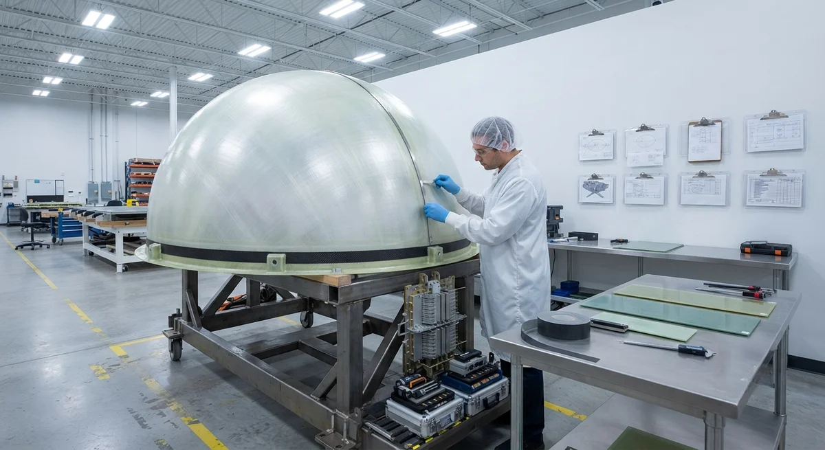
A radome — a contraction of "radar" and "dome" — is the protective housing that encloses an aircraft's weather radar, navigation antenna, or communication system. It is unique among aerospace structures because it must satisfy three demanding requirements simultaneously. The radome must
Introduction
A radome — a contraction of "radar" and "dome" — is the protective housing that encloses an aircraft's weather radar, navigation antenna, or communication system. It is unique among aerospace structures because it must satisfy three demanding requirements simultaneously. The radome must carry aerodynamic and pressurization loads; it must survive lightning attachment currents and high-velocity bird strikes; and it must let radar waves pass through with minimal attenuation or distortion. These demands pull the material in opposite directions. The first two favor strong, stiff, damage-tolerant composites. The third requires the material to be as transparent to electromagnetic waves as possible.
Carbon fiber composites are the stiffest and lightest structural materials available to aerospace engineers, but carbon fibers are electrically conductive. In a radome, that conductivity reflects and scatters radar energy, producing unacceptable insertion loss and beam distortion. The design challenge for a carbon fiber radome is therefore not simply load bearing — it is engineering a hybrid structure that keeps the loads in carbon fiber while using dielectric "windows" and a careful fiber architecture to keep the aperture transparent. This article examines how that balance is achieved, the lightning protection systems required, and the way carbon fiber structures are qualified against bird strike.
Why a Radome Must Be Electromagnetically Transparent
Radar performance is governed by two parameters that the radome directly influences: insertion loss and boresight error. Insertion loss is the fraction of radar energy lost as waves pass through the wall; boresight error is the angular deviation of the radar beam caused by refraction through a curved, multilayer wall. For a nose radome, typical requirements are an insertion loss below 0.5 dB and a boresight error of less than 0.1 degree across the scan envelope. The table below summarizes typical dielectric requirements for a Boeing-class nose radome:
| Parameter | Typical Requirement | Why It Matters |
|---|---|---|
| Insertion loss | < 0.5 dB | Every decibel lost cuts radar range roughly 12% |
| Boresight error | < 0.1 degree | Beam deviation mislocates targets and offsets tracking |
| Wall thickness tolerance | < ±0.1 mm | Variation shifts the electrical half-wave thickness |
| Dielectric constant (target) | 3.0–4.5 (engineered laminate) | Determines reflectance and matching-layer design |
| Loss tangent (target) | < 0.02 | Heat dissipation in the wall absorbs radar energy |
Solid carbon fiber is a near-perfect conductor, so a fully carbon radome wall would behave like a metal shield in front of the antenna, reflecting nearly all radar energy. To make carbon fiber usable in a radome, designers must introduce dielectric regions where radar waves pass freely, or create fiber architectures so sparse that the conductivity no longer forms a continuous shielding layer.
Carbon Fiber Architectures for Radomes
Several approaches incorporate carbon fiber into a radome wall while preserving transparency, and each trades structural performance against electrical performance:
- Dielectric window construction: The radome shell is built primarily from aramid or glass-fiber dielectric laminate, with carbon fiber used only in narrow structural "frames" or doublers at the base ring, mount bosses, and attachment lugs where loads concentrate. The radar aperture over the antenna remains carbon-free.
- Low-area-density carbon scrim: A very open carbon fabric — an area density of 40–80 g/m² versus 200 g/m² for a standard structural weave — is co-cured into a glass/aramid laminate. At low density the carbon filaments do not form continuous conductive paths, so reflectivity stays low while stiffness rises modestly.
- Carbon fiber banding: Unidirectional carbon tows are applied along the hoop and axial directions as stiffening bands, separated by dielectric laminate. The bands carry the dominant membrane loads while the dielectric fields between them remain transparent.
- Hybrid woven fabric: A fabric with a defined ratio of carbon and glass/quartz tows (for example, 15–25% carbon) balances stiffness against conductivity, with the carbon content tuned to the radar band and the required load.
For high-frequency radars operating above roughly 8 GHz, even low carbon content becomes problematic, and designers favor the dielectric window or banded approaches that keep carbon out of the main aperture entirely. The selection is always a system-level decision that weighs radar range against structural margin.
Lightning Strike Protection
Composite radomes carry a specific lightning risk: a strike attaches to the nose, the most likely attachment point on an aircraft. Because the composite wall is non-conductive or only partially conductive, the energy must be conducted away by a dedicated system rather than by the structure itself. Two protection layers are standard:
- External conducting diverter strips: Metal strips (usually aluminum or bronze, or a segmented system) run axially from the nose cap to the airframe along the outside surface. They capture the attachment point and guide the current path to the airframe ground, keeping the discharge off the dielectric surface. Divider spacing is designed so no point on the radome is more than a defined distance from a strip.
- Radome solid state diverter (or segmented strips): Modern nose radomes use segmented or solid-state diverters that bleed charge gradually to reduce damage and improve radar transparency, mounting them at the base or around the aperture to avoid blocking the active radar zone.
When a strike attaches to a carbon fiber band or frame, the high current (typically 100–200 kA for a Zone 1A strike) can vaporize resin and delaminate plies at the attachment point. Protective measures include a thin conductive mesh or conductive paint layer near the surface to spread the current, and structural doublers at attachment zones. Qualification follows aerospace lightning standards (for example, SAE ARP 5412) with waveform A (200 kA peak) and waveform B (2 kA) strike tests plus post-strike proof-voltage testing of the antenna system.
Bird Strike Resistance
Radomes are forward-facing and therefore among the structures most often struck by birds. Bird strike certification reflects the full lightning and bird-strike regime: the radome must retain enough residual strength after a strike that hazardous fragments do not enter the cockpit or damage downstream systems. Carbon fiber's high specific stiffness helps resist penetration at the leading edge, but its brittleness means the design must manage impact energy through the sandwich core and the laminate's energy-absorbing behavior.
Typical radome construction is a sandwich: thin carbon/glass outer and inner skins bonded to a lightweight honeycomb core. Under impact, the core crushes and absorbs energy, the skins flex and store strain energy, and the composite's relatively low elongation (1.5–2.0% for typical epoxies) means the panel deflects rather than tearing suddenly. Finite-element bird models simulate the response, and the structure is then validated against the applicable bird strike requirement (for example, the probability of a critical bird strike on the nose under the transport-aircraft rules, or the defined bird mass and speed for a given aircraft category).
Material Selection Trade-Offs
The choice between carbon, glass, aramid, and quartz fibers defines the radome's balance of stiffness, transparency, and cost, as summarized below:
| Fiber | Relative Stiffness | Dielectric Transparency | Moisture Absorption | Typical Radome Role |
|---|---|---|---|---|
| Carbon fiber | Very high | Conductive — used sparingly | Low | Structural frames, stiffening bands, doublers |
| Quartz fiber | Moderate | Excellent (best transparency) | Very low | High-frequency transparent skin |
| Aramid (para-aramid) | Moderate | Good | Higher (must be sealed) | Light, tough outer skin |
| E-glass | Low-moderate | Good | Low-medium | Cost-effective dielectric skin |
In practice, a production nose radome is a hybrid: carbon fiber carries the concentrated loads at the base, brows, and lugs; glass or aramid provides the dielectric skin; and in some designs a thin carbon scrim adds stiffness without losing transparency. Anti-erosion paint and a hydrophobic surface coating are normally applied to the outer skin to protect against rain erosion at high speed and to reduce contamination that would raise insertion loss.
Frequently Asked Questions
Why is carbon fiber both ideal and problematic for radomes?
Carbon fiber is ideal because it offers the highest specific stiffness of any structural composite, so it makes a radome light and stiff, and it survives repeated lightning and bird strike loading well. It is problematic because carbon fibers are electrically conductive. In a radome, that conductivity reflects and scatters radar energy, raising insertion loss and corrupting the beam. The engineering solution is not to abandon carbon fiber but to use it selectively — in structural bands, frames, and local doublers — while keeping the radar aperture in transparent glass, aramid, or quartz laminate.
How thick is a radome wall, and why is that thickness critical?
Wall thickness ranges from roughly 3 mm to 12 mm depending on aircraft size, structural loads, and radar band. The thickness is electrically critical because the radome wall is often designed as a half-wave or quarter-wave matching layer: the wall acts as a transmission filter whose performance depends on its electrical thickness, which is the physical thickness multiplied by the square root of the dielectric constant. A 0.1 mm variation can shift the electrical thickness enough to raise insertion loss noticeably, which is why component thickness is controlled tightly and why the finished wall is typically verified by swept-frequency measurement.
How is a composite radome protected against lightning?
Lightning protection uses diverters and current spreading. Metal diverter strips run from the nose cap along the outer surface to the airframe, capturing the strike attachment and channeling the current to ground so it does not damage the dielectric surface. These may be conventional metal strips or segmented solid-state diverters that bleed charge gradually for better radar transparency. Around conductive carbon regions, a thin metal mesh or conductive coating spreads current to prevent localized delamination, and structural doublers are added at attachment zones. The assembly is qualified to aerospace lightning standards with high-current strike tests followed by post-strike antenna proof testing.
Conclusion
Carbon fiber aircraft radomes reconcile two opposing requirements — structural strength and radar transparency — through selective fiber architecture. Carbon carries the concentrated loads at the base and attachment points, while glass, aramid, or quartz skins keep the radar aperture transparent; dedicated lightning diverters and energy-absorbing sandwich cores manage the strikes that nose-mounted structures inevitably face. The result is a structure that is simultaneously a load-bearing shell, an electromagnetic window, and a penetration-resistant shield.
For engineers designing or upgrading radomes and other radome-adjacent composite structures, the practical decisions are fiber selection, the placement of carbon reinforcement relative to the electrical aperture, and lightning/bird-strike qualification. Explore our carbon fiber fabrics and hybrid reinforcement options for radome-adjacent structural applications, or contact our engineering team to discuss material selection and structural qualification for your program.
Part of topic
Related Articles
- Carbon Fiber Tube for Sale: Comparing Listings and Avoiding Bad Specs
- Carbon Fiber Engine Parts: High-Temperature Performance for Racing and Performance Vehicles
- Carbon Fiber Body Parts: Automotive Exterior Panels and Structural Components
- Carbon Fiber Drone Body Manufacturing: Monocoque Design and Production Methods
- Carbon Fiber Drone Parts Supplier: FPV Frames, Arms and Structural Components
- Filament Wound Epoxy Tubes: Industrial Applications from Oil and Gas to Aerospace
Interested in Our Products?
Contact our team for competitive pricing and technical specifications.
Get a QuoteRelated Products

Carbon fiber standard plate-3k stripe
Lightweight, ultra-rigid standard sheets for drone fuselages, robot housings, facades and structural applications.

Carbon Fiber Plate — 3K Twill T700 3.0mm
Medium-thickness 3.0mm carbon fiber plate offering significantly higher load capacity while maintaining attractive 3K twill finish. Suitable for structural brackets, reinforcement plates, and load-bearing panels.

Carbon Fiber Plate — 3K Twill T700 1.5mm
Thin 1.5mm carbon fiber plate with 3K twill weave surface. Lightweight and stiff, commonly used for covers, panels, drone bodies, and applications requiring a premium aesthetic appearance.

Square Carbon Fiber Tube — 3K Twill T700
Square cross-section carbon fiber tube manufactured with 3K twill weave for torsional strength. Preferred for structural frames, trusses, and support columns where rectangular geometry offers design flexibility.

Carbon Fiber Plate — UD Unidirectional T700
Unidirectional carbon fiber plate with all fibers oriented in a single direction for maximum strength along the fiber axis. Essential for structural reinforcements, splints, and applications where load direction is predictable.