
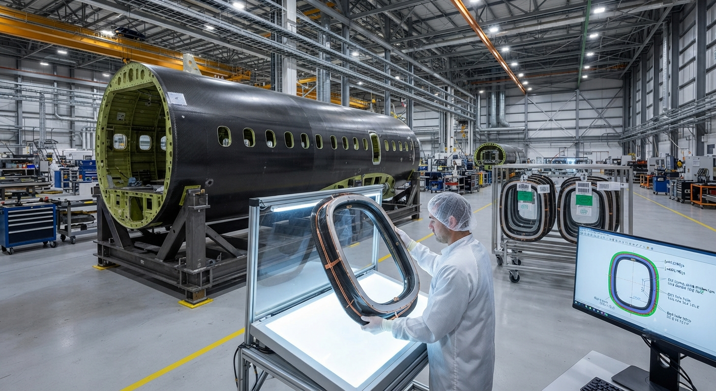
An in-depth B2B technical analysis of carbon fiber window frames in commercial and military aircraft. This article examines structural integration challenges with metallic fuselage interfaces, lightning strike protection strategies, pressurization cycle fatigue performance, OEM certification require
Introduction
Aircraft window frames represent one of the most structurally demanding components in the fuselage pressure boundary. Each window cutout creates a stress concentration in the pressurized fuselage skin, and the window frame must redistribute these loads while maintaining a leak-proof seal through tens of thousands of pressurization cycles. The transition from traditional aluminum alloy window frames to carbon fiber reinforced polymer (CFRP) alternatives presents unique engineering challenges that require systematic solutions in structural integration, electrical conductivity, and certification.
Modern commercial aircraft such as the Boeing 787 Dreamliner and Airbus A350 XWB have pioneered the use of CFRP fuselage barrels, creating a natural incentive to replace aluminum window frames with composite equivalents to eliminate galvanic corrosion issues, reduce part count, and improve overall structural efficiency. However, the path to certification of CFRP window frames has required extensive testing programs spanning more than 100,000 simulated flight cycles, full-scale lightning strike tests at 200 kA peak currents, and the development of specialized inspection techniques.
This article provides a technical examination of the key engineering considerations for CFRP aerospace window frames, with real data from OEM qualification programs and comparative analysis of alternative design approaches.
| Parameter | Aluminum Alloy (7075-T6) | CFRP (IM7/8552) | Unit |
|---|---|---|---|
| Density | 2.81 | 1.58 | g/cm³ |
| Weight per window frame (typical narrow-body) | 1.8–2.2 | 0.9–1.3 | kg |
| Tensile strength | 572 | 2,240 | MPa |
| Young's modulus | 71.7 | 164 | GPa |
| Electrical conductivity (through-thickness) | 18–23 × 10⁶ | 0.1–1.0 | S/m |
| CTE (coefficient of thermal expansion) | 23.6 | −0.5 to 2.5 (anisotropic) | ppm/°C |
| Fatigue endurance limit (10⁷ cycles) | 170–200 | 350–500 (tension-tension) | MPa |
| Galvanic corrosion with aluminum fuselage | None | Requires isolation layer | — |
| Manufacturing cycle time (per frame) | 2–4 hours (machined) | 4–8 hours (RTM + cure) | hours |
| OEM qualification test cycles | 60,000–80,000 | 100,000–160,000 | cycles |
Structural Integration Challenges
The interface between a CFRP window frame and the surrounding fuselage structure presents the first major engineering challenge. In an all-composite fuselage, the window frame must be co-bonded or secondarily bonded to the skin panel, creating a load path that must accommodate both in-plane shear loads from fuselage bending and pressurization-induced out-of-plane loads at the frame-to-skin junction. The stiffness mismatch between the orthotropic CFRP frame and the quasi-isotropic skin laminate requires careful ply transition design to avoid peel stress concentrations at the bond line.
For hybrid fuselage designs where CFRP window frames are installed in metallic fuselage sections—common in retrofit programs and certain military platforms—the differential thermal expansion between the CFRP frame and the aluminum or titanium surrounding structure must be explicitly managed. At operating temperatures ranging from −55°C at cruise altitude to +85°C on the tarmac in desert conditions, the aluminum structure expands approximately 23 ppm/°C while the CFRP frame may exhibit near-zero or even negative expansion in the fiber direction. This mismatch generates thermally induced stresses at the bolted or bonded interface that must be accounted for in the static strength and fatigue analysis.
The design solution typically involves incorporating a metallic interface ring—often a titanium or corrosion-resistant steel insert—that is co-cured or bonded into the CFRP frame. This metallic insert provides a thermally compatible attachment surface and distributes the fastener bearing loads over a larger area of the composite laminate. Industry practice for narrow-body aircraft uses interface rings of 3–5 mm thickness, with bearing stress limits for CFRP laminates typically set at 250–350 MPa under ultimate load conditions.
Lightning Strike Protection Strategies
Aircraft window frames are located in lightning strike Zone 1A and 1B on the fuselage, meaning they face a direct attachment point probability of up to 10⁻³ per flight hour. The lightning protection strategy for CFRP window frames must address two distinct threats: direct structural damage from the lightning arc attachment, and indirect electromagnetic effects on cabin electronics and window heating systems.
The fundamental challenge is that CFRP has through-thickness electrical conductivity of only 0.1–1.0 S/m—approximately eight orders of magnitude lower than aluminum at 18–23 × 10⁶ S/m. Without mitigation, a 200 kA lightning current would generate insufficiently distributed current density, leading to localized Joule heating exceeding 3000°C at the attachment point, resulting in matrix pyrolysis, fiber vaporization, and potential breach of the pressure boundary.
- Expanded copper foil (ECF) protection: The most widely adopted approach, using 2–4 oz/ft² (68–136 g/m²) copper foil embedded in the outer ply stack. Typical ECF layers are 0.05–0.10 mm thick and provide surface conductivity of 10⁵–10⁶ S/m. The foil must be electrically bonded to the surrounding fuselage structure through dedicated bond straps at a minimum of four locations per window frame, each providing a current path of less than 2.5 mΩ impedance. Boeing's 787 Dreamliner uses ECF protection on all composite window frames, with bond straps tested to 100 kA per MIL-STD-464.
- Aluminum flame spray coating: Applied as a 0.15–0.50 mm thick coating of pure aluminum onto the outer surface of the CFRP frame. Provides conductivity of 10⁶–10⁷ S/m and offers the advantage of conformal coverage around complex geometries without requiring pre-cured foil placement. Airbus has qualified flame spray for certain A350 composite frame components. The primary disadvantage is process control — coating thickness uniformity must be maintained within ±0.05 mm over large surface areas.
- Conductive primer and paint systems: Low-cost alternative providing surface conductivity of 10³–10⁴ S/m, sufficient for static charge dissipation but inadequate for direct lightning attachment. These systems are used exclusively in combination with primary metallic protection layers, serving as a secondary current path and corrosion barrier.
- Embedded metallic mesh: Woven or expanded metal mesh (copper or aluminum) co-cured into the outer 2–3 plies of the laminate. Mesh densities of 100–200 g/m² provide comparable lightning protection to solid foil while allowing improved interlaminar bond strength through mechanical interlock. Used on Bombardier CSeries and Mitsubishi SpaceJet window surrounds.
Pressurization Cycle Fatigue Performance
The fatigue performance of CFRP window frames under repeated pressurization cycles is arguably the most critical aspect of certification. A commercial aircraft experiences approximately one pressurization cycle per flight, translating to 60,000 to 100,000 cycles over a 25–30 year service life for typical narrow-body operations, and up to 160,000 cycles for high-utilization short-haul aircraft.
Fatigue testing of CFRP window frames has demonstrated that properly designed composite frames exhibit significantly longer fatigue life than their aluminum predecessors, primarily due to the absence of a fatigue endurance limit in the fiber direction and the progressive nature of damage accumulation in composite laminates. The critical failure mode is not catastrophic fracture as in metallic frames, but rather progressive matrix cracking, delamination growth, and eventual stiffness degradation that leads to seal leakage.
Damage tolerance certification per FAR 25.571 requires demonstration that the window frame can sustain damage equivalent to a 100 mm visible impact damage (VID) event followed by an additional two design service periods without failure. For CFRP frames, this typically translates to demonstrating continued airworthiness after a 100 J impact event—simulating tool drop or runway debris strike—followed by 40,000 additional pressurization cycles at 1.5 times the design limit pressure. Test data from the Boeing 787 certification program showed CFRP window frames surviving 126,000 cycles after VID without catastrophic failure, with seal leakage occurring at 98,000 cycles as the first detectable failure indicator.
FAA and EASA Certification Requirements
Certification of CFRP window frames follows the same airworthiness regulations as metallic equivalents but requires additional substantiation specific to composite structures under FAR 25.571 (damage tolerance) and AC 20-107B (composite aircraft structure). The following requirements apply specifically to composite window frames:
| Requirement | Aluminum Frame | CFRP Frame | Test Method |
|---|---|---|---|
| Limit load static test | 1.0 × design limit | 1.0 × design limit | Pressure box test |
| Ultimate load static test | 1.5 × design limit | 1.5 × design limit | Pressure box test |
| Fatigue test cycles | 60,000–80,000 | 100,000–160,000 | Cyclic pressure |
| Impact damage threshold | Not required separately | 100 J (VID), 50 J (BVID) | Drop weight impactor |
| Residual strength after impact | N/A | ≥1.0 × limit load | Static after impact |
| Lightning strike test current | Not required (conductive) | 200 kA (Zone 1A) | Full-scale test |
| Environmental conditioning | Not critical | CTD/ETD (wet/dry) | Climatic chamber |
| Bird strike (if applicable) | Standard requirement | Standard requirement | Gas gun test |
Manufacturing Approaches
Three primary manufacturing routes have been qualified for CFRP window frame production, each offering different trade-offs between cycle time, capital investment, and mechanical performance.
Resin Transfer Molding (RTM) is the most widely adopted process, accounting for approximately 65% of CFRP window frame production globally. RTM produces near-net-shape frames with excellent surface finish on both tool and bag sides, eliminating the need for post-mold machining of contoured surfaces. Typical RTM cycle times for window frames are 90–120 minutes of injection at 120–180°C, followed by 120–180 minutes of cure at the same temperature. Key suppliers including GKN Aerospace and Spirit AeroSystems operate RTM cells dedicated to window frame production.
Compression Molding (CM) offers faster cycle times of 20–45 minutes per frame by using pre-impregnated charge placed in a heated matched die set. The higher capital cost of compression tooling—approximately 2–3 times that of RTM tooling—is offset by the faster cycle, making CM economically attractive for production volumes exceeding 1,000 frames per year. The trade-off is reduced fiber volume fraction (52–57% vs 55–60% for RTM) and consequently slightly lower mechanical properties.
Automated Fiber Placement (AFP) followed by autoclave cure is used for the highest-performance applications, typically in military aircraft and business jets where weight savings justify the higher manufacturing cost. AFP delivers the highest fiber volume fractions (60–65%) and the most precise fiber orientation control, enabling locally tailored layups that optimize the frame's load path. The cycle time (including autoclave cure) is 8–16 hours per frame, significantly longer than RTM or CM.
Conclusion
CFRP aerospace window frames have matured from experimental concepts to certified production components on the world's most advanced commercial aircraft. The engineering challenges—structural integration with metallic interfaces, lightning strike protection, pressurization fatigue performance, and certification—have been systematically addressed through a combination of innovative design solutions, extensive test programs, and manufacturing process development.
The weight savings of 30–45% per frame compared to aluminum equivalents, multiplied across 80 to 250 windows per aircraft, deliver meaningful aircraft-level fuel burn reductions. For narrow-body aircraft with approximately 80 windows, the total weight saving of 40–60 kg across all frames translates to an estimated fuel saving of 8,000–12,000 kg of jet fuel over a 60,000-cycle service life, corresponding to approximately 25–38 metric tons of CO₂ emissions reduction per aircraft.
For B2B suppliers evaluating entry into the CFRP window frame market, the key success factors are investment in automated manufacturing (RTM or AFP), partnership with an OEM for certification data sharing, and the development of in-house lightning strike testing capability. The market for composite aircraft window frames is projected to grow at 8–10% CAGR through 2035, driven by increasing composite fuselage adoption in next-generation single-aisle aircraft programs.
FAQ
Can CFRP window frames be repaired in-service, or must they be replaced?
CFRP window frames are typically classified as replace-on-condition rather than repairable. Minor surface damage limited to the paint and copper foil layer can be restored through local re-finishing. However, any damage penetrating into the structural laminate — including matrix cracking, delamination, or fiber breakage — requires frame replacement. The bonded metal interface ring further complicates repair because the thermal cure cycle required for composite repair patches would degrade the interface bond. OEM maintenance manuals explicitly prohibit structural repair of primary load-bearing composite frames and specify replacement intervals based on inspection findings. This contrasts with aluminum frames, which can be welded or reworked extensively.
How does the cost of CFRP window frames compare to aluminum equivalents?
Current production CFRP window frames cost 1.5 to 2.8 times more than equivalent aluminum frames, depending on manufacturing process complexity and production volume. At low volumes (under 500 frames per year), RTM-processed CFRP frames cost approximately $450–$650 per frame compared to $180–$280 for machined aluminum 7075-T6 frames. At high volumes exceeding 5,000 frames per year, RTM costs drop to $220–$350 per frame, while compression molded CFRP can reach $190–$280 per frame — approaching parity with aluminum. The total ownership cost calculation must include the weight saving benefit (approximately $200–$500 per kg saved over the aircraft life, depending on fuel prices and utilization) and the elimination of corrosion inspection and rework costs that apply to aluminum frames in composite fuselage environments.
What is the certification path for a new CFRP window frame design?
The certification of a CFRP window frame follows a structured process defined by the OEM's design organization approval (DOA) and the relevant airworthiness authority (FAA, EASA). The typical timeline spans 24 to 36 months from design freeze to final certification, comprising four phases: (1) Coupon-level testing (6 months) — 1,500–3,000 test specimens establishing A-basis design allowables for the specific material system, layup, and process parameters. (2) Element and subcomponent testing (8–12 months) — 200–500 tests of frame-to-skin joints, fastener pull-through, and lightning attachment coupons. (3) Full-scale component testing (6–9 months) — static, fatigue (100,000+ cycles), and residual strength testing of complete frame assemblies in a pressure box. (4) Full-scale aircraft integration (6–9 months) — lightning strike test at 200 kA, bird strike test (if applicable), and production validation on a conforming article. The OEM typically bears 70–80% of the certification cost, while the Tier 1 supplier provides the manufacturing process qualification data.
Part of topic
Related Articles
- Carbon Fiber Mooring for Floating Offshore Wind: Fatigue and Corrosion in Deep Water
- Carbon Fiber Bicycle Frame Optimization: Layup Design and Manufacturing for Competitive Racing
- Carbon Fiber CFRP Retrofit for Infrastructure: Bridge and Building Seismic Strengthening
- Carbon Fiber Medical Imaging Equipment: Lightweight Gantry and Couch Structures for MRI/CT
- Carbon Fiber EV Battery Enclosures: Crash Safety and Electromagnetic Shielding Design
- Carbon Fiber Structures for Low-Altitude Economy: UAV Airframes and eVTOL Components
Interested in Our Products?
Contact our team for competitive pricing and technical specifications.
Get a QuoteRelated Products

Carbon fiber standard plate-3k stripe
Lightweight, ultra-rigid standard sheets for drone fuselages, robot housings, facades and structural applications.

Square Carbon Fiber Tube — 3K Twill T700
Square cross-section carbon fiber tube manufactured with 3K twill weave for torsional strength. Preferred for structural frames, trusses, and support columns where rectangular geometry offers design flexibility.

Carbon Fiber Plate — 3K Twill T700 3.0mm
Medium-thickness 3.0mm carbon fiber plate offering significantly higher load capacity while maintaining attractive 3K twill finish. Suitable for structural brackets, reinforcement plates, and load-bearing panels.

Carbon Fiber Plate — 3K Twill T700 1.5mm
Thin 1.5mm carbon fiber plate with 3K twill weave surface. Lightweight and stiff, commonly used for covers, panels, drone bodies, and applications requiring a premium aesthetic appearance.

Carbon Fiber Plate — UD Unidirectional T700
Unidirectional carbon fiber plate with all fibers oriented in a single direction for maximum strength along the fiber axis. Essential for structural reinforcements, splints, and applications where load direction is predictable.