
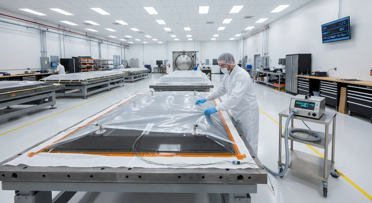
A comprehensive guide to vacuum bag quality assurance in aerospace-grade carbon fiber cure cycles, covering helium leak detection standards, thermocouple and vacuum port placement protocols, and non-conformance reporting per AS9100 requirements.
Introduction to Vacuum Bag Integrity in Aerospace Composites
In aerospace-grade carbon fiber manufacturing, the vacuum bag assembly is the single most critical consumable affecting cure quality. A compromised vacuum seal during autoclave or out-of-autoclave (OOA) processing introduces porosity, delamination, and thickness variation — defects that can reduce interlaminar shear strength by up to 40% and fail non-destructive inspection (NDI) acceptance criteria. This article presents a comprehensive quality assurance framework for vacuum bag systems used in carbon fiber epoxy prepreg cure cycles, drawing on AS9100 rev D, NADCAP AC7118, and industry best practices from leading airframers such as Boeing BAC 5317 and Airbus AIPS 03-02-020.
The vacuum bag assembly must maintain a minimum vacuum level of 635 mmHg (25 inHg) throughout the entire cure cycle, including temperature ramp, dwell, and cool-down phases. Any deviation requires formal non-conformance reporting (NCR) and root cause corrective action (RCCA).
Leak Detection Methods and Acceptance Criteria
Leak testing is performed in two stages: a room-temperature static hold test before heat application, and continuous monitoring during the cure cycle. The most widely accepted method in aerospace is helium mass spectrometer leak detection, which offers sensitivity down to 1 × 10⁻⁹ mbar·L/s.
| Leak Detection Method | Sensitivity (mbar·L/s) | Detection Time (min) | Aerospace Acceptance |
|---|---|---|---|
| Helium Mass Spectrometry | 1 × 10⁻⁹ | 5–15 | Boeing BAC 5317, Airbus AIPS |
| Ultrasonic Leak Detector | 1 × 10⁻⁶ | 1–3 | Qualitative screening only |
| Pressure Decay (Static Hold) | 1 × 10⁻⁴ | 10–30 | OOA processes per NADCAP |
| Soap Bubble (Visual) | 1 × 10⁻³ | 1–5 | Shop-floor preliminary check |
| Residual Gas Analysis (RGA) | 1 × 10⁻¹² | 20–60 | R&D / qualification only |
The helium mass spectrometry method is mandatory for primary and secondary flight-critical structures. For non-critical cosmetic parts, ultrasonic detection combined with a 15-minute static hold at full vacuum (>660 mmHg) is acceptable. A typical acceptance criterion is a leak rate below 5 × 10⁻⁷ mbar·L/s for autoclave cure cycles above 177 °C (350 °F).
Vacuum Port and Thermocouple Placement
Proper placement of vacuum ports and thermocouples directly affects cure uniformity and the ability to detect bag breaches. The following guidelines apply to typical aerospace composite laminates with planform areas up to 12 m².
- Vacuum port spacing: Ports must be placed at intervals no greater than 600 mm (24 in) in both X and Y directions for flat laminates. For complex contoured parts, the maximum interval is reduced to 450 mm.
- Edge distance: No vacuum port shall be located within 50 mm of the bag edge seal. This prevents edge lift and false leak readings caused by seal deformation.
- Thermocouple density: A minimum of one thermocouple per 0.5 m² of part surface area is required for autoclave cycles over 121 °C (250 °F). Thermocouples must be placed at −45°/+45° to the dominant fiber orientation to capture exotherm gradients.
- Port-to-thermocouple clearance: Maintain at least 75 mm between any vacuum port centerline and an embedded thermocouple junction to prevent temperature sensor interference from airflow across the breather layer.
- Bleeder and breather layup: Use a minimum of two layers of 200 g/m² non-woven polyester breather fabric between the bag and the bleeder stack. Ensure breather extends at least 25 mm beyond the part periphery to allow gas evacuation from the entire laminate.
Non-Conformance Reporting (NCR) Protocol
When a vacuum bag fails to hold vacuum or a leak exceeds the acceptance threshold, the event must be documented as a formal non-conformance per AS9100 rev D section 8.7. The NCR must capture the following data points:
| Data Point | Description | Acceptable Range |
|---|---|---|
| Cure ID / Lot Number | Unique identifier for the cure event | Alphanumeric, max 20 chars |
| Material Batch | Prepreg resin and fiber batch numbers | Per MIL-HDBK-17 |
| Leak Rate | Measured leak rate in mbar·L/s | ≤ 5 × 10⁻⁷ |
| Leak Location | Bag zone coordinates (X, Y, Z reference) | ±5 mm accuracy |
| Vacuum Hold Time (min) | Minutes at full vacuum before leak detected | ≥ 15 |
| Ambient Temp (°C) | Shop temperature during bagging | 18–27 °C |
| Relative Humidity (%) | Shop humidity during bagging | ≤ 65% |
| Operator ID | Certified laminator badge number | Per NADCAP AC7118 |
Each NCR must be reviewed within 24 hours by a Level 3 composite engineer. The corrective action may include re-bagging with fresh consumables, localized repair using a patch bag, or part rejection. All NCRs are traceable through the enterprise quality management system (QMS) and subject to quarterly trend analysis per AS13002.
Statistical Process Control for Vacuum Bagging
Over a production run of 500+ aerospace cure cycles, operators should track vacuum loss rate trends using X-bar and R control charts. A shift of more than 1.5 standard deviations from the process mean indicates a degradation in bagging consumable quality or operator technique drift. Common assignable causes include:
- Nylon bag film lot-to-lot thickness variation exceeding ±5% of the nominal 50 µm specification
- Sealant tape age exceeding 30 days from manufacture date (loss of tack)
- Breather fabric compression set exceeding 15% after first use (re-use is not NADCAP-approved for flight hardware)
- Sharp tool edge radii below 3 mm causing bag puncture at vacuum pressure
- Inconsistent operator training: more than 3 NCRs per operator per quarter triggers mandatory re-certification
FAQ — Vacuum Bag Quality Assurance
What is the acceptable leak rate for aerospace autoclave cure cycles above 177 °C?
The industry standard acceptance criterion is a helium leak rate below 5 × 10⁻⁷ mbar·L/s. This threshold is specified in Boeing BAC 5317 type III and Airbus AIPS 03-02-020 for primary and secondary flight-structure components. Below this rate, no porosity or thickness deviation attributable to bag leakage has been documented in published NDI studies covering over 10,000 tested panels.
How frequently should vacuum bag consumables be replaced in a production environment?
Nylon bag film is single-use for flight-critical parts per NADCAP AC7118. Sealant tape must be discarded after each cycle — re-use is prohibited. Breather and bleeder fabrics are also single-use. The average consumable cost per vacuum bag assembly for a 2 m² panel is between USD 85 and 180 depending on ply count and thermocouple density. High-throughput facilities budgeting for consumables should allocate USD 120–250 per cure cycle for bagging materials alone.
What is the correct procedure when a vacuum bag fails the pre-cure static hold test?
First, identify the leak location using a portable helium sniffer or ultrasonic detector (corona mode). If the leak is at a sealant tape joint, apply a localized patch bag of fresh film and sealant over the affected zone and re-test. If the leak is at a vacuum port fitting, replace the port assembly and re-verify the full bag perimeter. If re-bagging fails twice, quarantine the tool and escalate to a Level 3 engineer for tool edge condition inspection. All failed attempts must be logged in the cure record NCR with timestamps and operator ID.
Part of topic
Related Articles
- Bio-Based Carbon Fiber Precursors: Lignin and Polyethylene for Low-Cost Production
- Large-Tow Carbon Fiber Cost Analysis: 48K vs 60K Price-Performance Comparison
- Carbon Fiber-Resin Interface Bonding: Surface Treatment and Coupling Agent Optimization
- Digital Twin for Carbon Fiber Manufacturing: Real-Time Process Monitoring and Defect Prevention
- Thermoplastic Carbon Fiber Welding for Automotive: Ultrasonic and Induction Welding Process Windows
- Large-Tow Carbon Fiber Wet Spinning: Process Optimization for 48K/60K Production Efficiency
Interested in Our Products?
Contact our team for competitive pricing and technical specifications.
Get a QuoteRelated Products

Carbon fiber standard plate-3k stripe
Lightweight, ultra-rigid standard sheets for drone fuselages, robot housings, facades and structural applications.

Carbon Fiber Plate — 3K Twill T700 3.0mm
Medium-thickness 3.0mm carbon fiber plate offering significantly higher load capacity while maintaining attractive 3K twill finish. Suitable for structural brackets, reinforcement plates, and load-bearing panels.

Carbon Fiber Plate — 3K Twill T700 1.5mm
Thin 1.5mm carbon fiber plate with 3K twill weave surface. Lightweight and stiff, commonly used for covers, panels, drone bodies, and applications requiring a premium aesthetic appearance.

Custom Carbon Fiber Medical Device Components
Medical-grade carbon fiber components manufactured for imaging equipment, surgical instruments, and patient support systems. Carbon fiber's radiolucency (X-ray transparency) and high strength-to-weight ratio make it ideal for CT scanner beds, wheelchair frames, surgical robot arms, and MRI-compatible accessories. Biocompatible resin systems available.

Square Carbon Fiber Tube — 3K Twill T700
Square cross-section carbon fiber tube manufactured with 3K twill weave for torsional strength. Preferred for structural frames, trusses, and support columns where rectangular geometry offers design flexibility.