
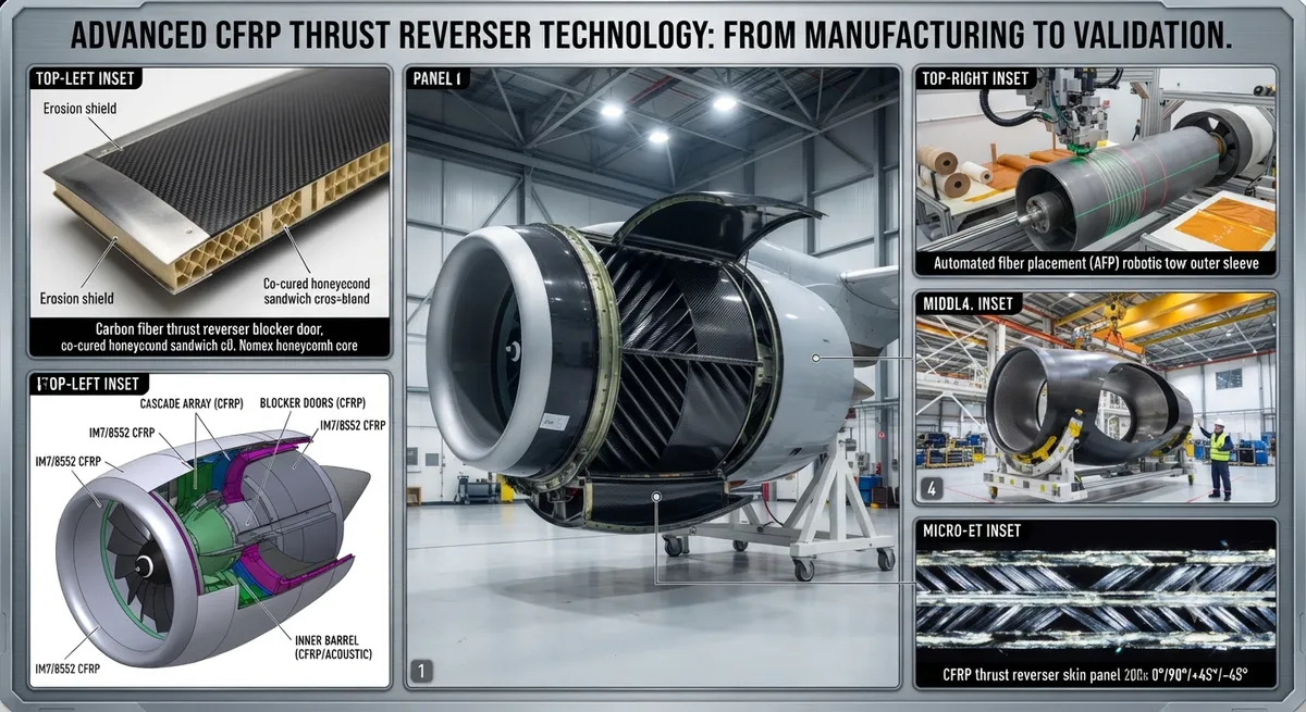
Explore how carbon fiber composites are revolutionizing thrust reverser designs in modern aerospace engine nacelle systems, delivering weight savings, thermal resistance, and structural integrity at extreme operating conditions.
Aircraft thrust reversers are among the most mechanically and thermally demanding components in a modern jet engine nacelle system. They must withstand extreme temperatures, high-cycle fatigue, bird strike loads, and fan-blade-out events while remaining lightweight enough to contribute to overall fuel efficiency. Carbon fiber reinforced polymer (CFRP) composites have become the material of choice for next-generation thrust reverser structures, replacing legacy aluminum and titanium assemblies with significant performance gains.
Design Requirements for Thrust Reverser Structures
The thrust reverser system redirects engine exhaust flow forward to generate deceleration force upon landing. This function creates a unique set of material demands:
- High-temperature resistance: Exhaust gas temperatures can reach 350–500°C (662–932°F) at the cascade area, requiring resin systems with high glass transition temperatures (Tg).
- Impact tolerance: The reverser must survive 4-lb bird strikes at cruise speeds and contain debris from uncontained engine failures.
- Dimensional stability: Translation sleeves and cascade segments must maintain tight clearances (0.5–1.5 mm) across a temperature range of −55°C to +120°C operating ambient.
- Weight sensitivity: Every kilogram saved on the nacelle reduces fuel burn by approximately 0.015% per flight cycle — a meaningful figure over a 60,000-cycle service life.
- Acoustic attenuation: The inner barrel of the reverser must incorporate acoustic treatment to meet Stage 5 noise regulations.
CFRP Material Grades for Thrust Reverser Applications
| Material Grade | Resin System | Tg (°C) | Tensile Modulus (GPa) | Typical Application | Weight vs. Al 2024 |
|---|---|---|---|---|---|
| IM7/8552 | Toughened epoxy | 182 | 165 | Cascade vanes, blocker doors | −38% |
| AS4/PR520 | High-temp epoxy | 210 | 140 | Translation sleeves | −32% |
| T800/3900-2 | Toughened BMI | 250 | 175 | Fan cowl inner panels | −40% |
| HTS40/977-2 | High-temp epoxy | 195 | 155 | Cascade support structure | −35% |
Manufacturing Processes
Thrust reverser components are predominantly manufactured using automated fiber placement (AFP), resin transfer molding (RTM), and compression molding. AFP is favored for large, doubly-curved components such as the outer sleeve and cascade ring, where precise fiber orientation control is critical. RTM is used for complex ribbed structures like blocker door linkages, achieving net-shape parts with minimal post-machining. Compression molding delivers high-volume, low-cost cascade vane arrays with consistent quality.
Thermal Management and Erosion Protection
Thrust reverser components in the hot-gas path face severe thermal and erosion challenges. The cascade exhaust plane — where redirected fan air mixes with core exhaust — experiences localized temperatures up to 200°C during reverse thrust operation, with transient spikes to 350°C during engine surge events. To protect the CFRP structure, a multi-layer erosion protection system is employed. The outermost layer consists of a plasma-sprayed titanium dioxide (TiO₂) ceramic coating (75–125 μm thick), applied over a nickel-aluminide bond coat (25–50 μm). Below this, a woven S-glass fabric ply (0.15 mm) provides thermal barrier and dielectric separation between the ceramic and the carbon fiber structure. The CFRP substrate itself uses a high-temperature BMI resin system (Tg > 250°C) in the hot-zone regions. This layered armor system has demonstrated erosion life exceeding 25,000 flight cycles in accelerated rig tests at representative sand and dust concentrations (50 mg/m³) per RTCA DO-160 section 12.0 requirements.
Case Study: CFM International LEAP Nacelle
The LEAP engine nacelle, certified in 2016 and now powering over 3,500 Airbus A320neo and Boeing 737 MAX aircraft, features a CFRP thrust reverser structure that weighs 27% less than the CFM56 equivalent. Key innovations include a co-cured one-piece O-duct outer sleeve, integrated acoustic panels bonded directly to the inner barrel, and a titanium erosion shield at the cascade exhaust plane. The reverser system demonstrated over 8,000 hours of flight testing with zero composite structural failures. The O-duct sleeve alone achieves a 31% weight saving over the aluminum baseline while maintaining identical stiffness and buckling resistance. Boeing reported a 0.7% improvement in block fuel burn directly attributable to nacelle weight reduction on the 737 MAX. The CFM56-to-LEAP transition has saved airlines an estimated total of 2.1 million metric tons of CO₂ across the global fleet as of Q2 2026, with nacelle composite weight reduction contributing approximately 14% of that saving.
Quality Assurance and Nondestructive Inspection
Given the flight-critical nature of thrust reverser structures, CFRP components undergo rigorous nondestructive inspection (NDI) throughout the manufacturing process. Automated ultrasonic C-scan inspection at 5–10 MHz detects delaminations, porosity (>1% void content), and disbonds in co-bonded and co-cured assemblies. Laser shearography is used for in-process inspection of honeycomb core-to-skin bondlines, with a sensitivity of 2.5 mm diameter disbonds. Phased-array ultrasonic testing (PAUT) at the cascade vane root attachments provides volumetric inspection of the critical bond-joint region. Post-cure coordinate measuring machine (CMM) inspection verifies aerodynamic profile conformance within ±0.5 mm across the 3-meter O-duct diameter. All NDI data is recorded in a part-specific digital twin that tracks every manufacturing parameter — resin batch ID, fiber lot number, cure cycle temperature profile, and ultrasonic attenuation maps — enabling traceability from raw material to installed component.
Frequency Asked Questions
What are the main failure modes of CFRP thrust reverser components?
The primary failure modes include matrix cracking from thermal cycling (typically after 15,000–20,000 cycles), delamination at bonded joint interfaces (especially at the cascade-to-sleeve bond line), and erosion of the leading-edge protective coating. Most failures are detected through scheduled borescope inspections and ultrasonic C-scan during heavy maintenance checks. Operators typically replace thrust reverser composite panels at 25,000–30,000 flight cycles.
Can carbon fiber thrust reversers be repaired in-service?
Yes. Most thrust reverser composite structures are designed with repair capability per the OEM's Structural Repair Manual (SRM). Typical field repairs include scarf repairs for impact damage (up to 25 mm diameter), bonded doublers for minor delaminations, and injection repairs for disbonds. Hot-bond repair equipment with vacuum bagging and thermal blankets is standard at major MRO facilities. Damage larger than 50 mm diameter typically requires component replacement.
How does CFRP compare to titanium for thrust reverser hot sections?
CFRP offers a 35–42% weight saving over titanium 6Al-4V in the same structural role. However, titanium retains a thermal advantage — it can withstand continuous exposure to 400°C without degradation, while even high-temperature BMI CFRP grades are limited to 230–260°C continuous service. For this reason, hot-section components near the exhaust nozzle (the last 8–12 inches of the cascade) still use titanium or nickel-alloy shields. The hybrid approach — CFRP structure with titanium edge protection — optimizes the weight-versus-thermal tradeoff.
Part of topic
Related Articles
- Carbon Fiber Mooring for Floating Offshore Wind: Fatigue and Corrosion in Deep Water
- Carbon Fiber Bicycle Frame Optimization: Layup Design and Manufacturing for Competitive Racing
- Carbon Fiber CFRP Retrofit for Infrastructure: Bridge and Building Seismic Strengthening
- Carbon Fiber Medical Imaging Equipment: Lightweight Gantry and Couch Structures for MRI/CT
- Carbon Fiber EV Battery Enclosures: Crash Safety and Electromagnetic Shielding Design
- Carbon Fiber Structures for Low-Altitude Economy: UAV Airframes and eVTOL Components
Interested in Our Products?
Contact our team for competitive pricing and technical specifications.
Get a QuoteRelated Products

Carbon fiber standard plate-3k stripe
Lightweight, ultra-rigid standard sheets for drone fuselages, robot housings, facades and structural applications.

Carbon Fiber Plate — 3K Twill T700 3.0mm
Medium-thickness 3.0mm carbon fiber plate offering significantly higher load capacity while maintaining attractive 3K twill finish. Suitable for structural brackets, reinforcement plates, and load-bearing panels.

Carbon Fiber Plate — 3K Twill T700 1.5mm
Thin 1.5mm carbon fiber plate with 3K twill weave surface. Lightweight and stiff, commonly used for covers, panels, drone bodies, and applications requiring a premium aesthetic appearance.

Square Carbon Fiber Tube — 3K Twill T700
Square cross-section carbon fiber tube manufactured with 3K twill weave for torsional strength. Preferred for structural frames, trusses, and support columns where rectangular geometry offers design flexibility.

Carbon Fiber Plate — UD Unidirectional T700
Unidirectional carbon fiber plate with all fibers oriented in a single direction for maximum strength along the fiber axis. Essential for structural reinforcements, splints, and applications where load direction is predictable.