
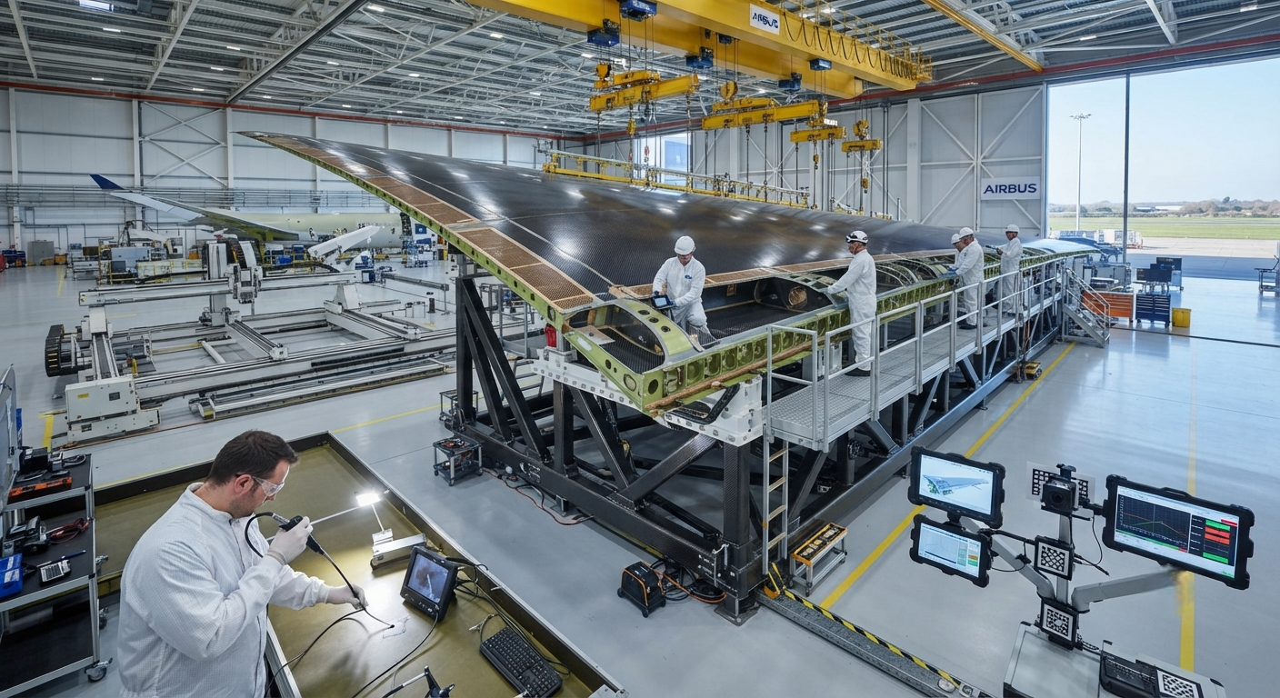
Engineering deep-dive on CFRP liquid fuel tanks for aerospace applications. Covers liner selection (aluminium, PEEK, linerless), lightning strike protection, fuel immersion resistance, manufacturing processes (autoclave prepreg, filament winding, AFP), and FAA/EASA certification requirements (14 CFR 25.981, AMC 20-29). Includes real-data comparison table across four tank designs.
The Growing Demand for Composite Fuel Tanks in Aerospace
The aerospace industry is increasingly turning to carbon fiber reinforced polymer (CFRP) liquid fuel tanks as a means of reducing structural weight, improving corrosion resistance, and enabling new aircraft configurations. From commercial aviation wing and fuselage integral tanks to business jet conformal tanks and emerging urban air mobility (UAM) vehicle fuel systems, carbon fiber fuel tanks offer a 30–50% weight reduction compared to traditional aluminium alloy tanks. However, the certification pathway for composite fuel tanks is one of the most demanding in aerospace engineering, requiring rigorous demonstration of leak-proof performance, lightning strike protection, fuel compatibility, and crashworthiness across the full operating temperature range.
This article examines the design principles, material selection criteria, manufacturing processes, and certification requirements for CFRP liquid fuel tanks in aerospace applications, providing engineering and procurement professionals with a comprehensive technical reference for evaluating composite fuel tank solutions.
Design Principles for Leak-Proof Composite Fuel Tanks
The fundamental challenge of composite fuel tank design is achieving and maintaining leak-proof integrity over the aircraft's service life — typically 30,000–60,000 flight cycles for commercial transport aircraft. Unlike metallic tanks where leak paths are limited to welded joints and sealant beads, composite tanks must contend with matrix microcracking, fibre-matrix debonding, and through-thickness permeation mechanisms that are unique to laminated materials.
- Integral fuel tank liners: The most widely adopted approach for commercial aviation is a thin metallic or thermoplastic liner (0.3–1.0 mm thick) that provides the primary fuel barrier, overwrapped with CFRP structure that carries the pressure and flight loads. Aluminium 2024-T3 or 6061-T6 liners are common for conventional aircraft; polyether ether ketone (PEEK) and polyetherimide (PEI) thermoplastic liners are increasingly specified for next-generation platforms due to their chemical resistance and thermoformability.
- Linerless composite designs: For applications where weight reduction is paramount — such as UAM vehicles, high-altitude pseudo-satellites (HAPS), and long-endurance UAVs — linerless composite tank designs eliminate the weight of the liner entirely. These designs rely on a biaxial carbon fibre layup with optimised fibre orientation to minimise resin-dominated through-thickness permeability. A resin system with low free volume and high crosslink density (such as cyanate ester or high-Tg benzoxazine) is essential. Linerless designs require an inner ply of fine-weave carbon fibre fabric (3K or 1K plain weave) with a resin-rich surface layer maintained at 60–80% resin content to seal the surface porosity.
- Co-bonded vs co-cured structures: Integral fuel tanks that form part of the wing or fuselage primary structure are typically co-bonded — the CFRP fuel tank structure is cured separately, then secondarily bonded or bolted to the surrounding airframe. Co-cured designs, where the tank and surrounding structure are cured in a single autoclave cycle, offer weight savings but introduce greater complexity in tooling, process control, and non-destructive inspection.
| Parameter | Aluminium 2024-T3 Integral Tank | CFRP with Aluminium Liner | CFRP with PEEK Liner | Linerless CFRP Tank |
|---|---|---|---|---|
| Weight (normalised to aluminium) | 1.00 | 0.65–0.75 | 0.55–0.65 | 0.45–0.55 |
| Leak-proof barrier mechanism | Welded joints + sealant | Aluminium liner | PEEK liner | Resin-rich layer + fine-weave fabric |
| Maximum operating temperature (°C) | 150 | 177 (epoxy-limited) | 250 | 200–300 (resin dependent) |
| Fatigue life (flight cycles) | 60,000–90,000 | 40,000–60,000 | 50,000–80,000 | 20,000–40,000 |
| Fuel compatibility (Jet A-1 / JP-8) | Excellent | Excellent | Excellent | Good (requires testing) |
| Manufacturing cost index | 1.0 (baseline) | 1.8–2.5 | 2.5–3.5 | 1.5–2.0 |
| Repairability in field | Welding + riveting | Bonded CFRP patch | Bonded CFRP patch | Bonded CFRP patch + surface seal |
| Certification status for primary structure | Fully certified (all platforms) | Certified (A350, B787 wing tanks) | In certification (2026–2028) | Limited (UAV, UAM only) |
Material Selection for Fuel Tank CFRP
The material system for a CFRP fuel tank must satisfy requirements that extend well beyond basic structural properties:
- Fuel immersion resistance: The resin matrix must not degrade, swell, or microcrack when continuously immersed in aviation fuel (Jet A-1, JP-8, or JP-5). Standard epoxy systems used in aircraft structures (such as Hexcel 8552 or Cycom 977-3) are generally fuel-resistant at room temperature, but at elevated temperatures (80–120°C) the fuel absorption rate increases significantly — from 0.5–0.8% weight gain at 23°C to 2.5–4.0% at 120°C after 1,000 hours immersion. Cyanate ester resins offer superior fuel resistance, with weight gains below 1.0% even at 120°C, at a cost premium of 50–80% over epoxy.
- Lightning strike protection (LSP): Fuel tank skins are among the most lightning-critical zones on an aircraft. Carbon fiber's electrical conductivity (approximately 600 S/m in-plane) is orders of magnitude lower than aluminium (35,000 S/m), meaning that a direct lightning strike can cause internal arcing, sparking, and fuel vapour ignition within an unprotected CFRP tank. The standard protection for CFRP fuel tanks is a 0.1–0.3 mm expanded copper foil (ECF) bonded to the outer surface of the tank skin, providing an electrical path of <25 mΩ per square. Aluminium flame spray coating (0.1–0.2 mm) is an alternative for wing skin surfaces. All fastener locations must include conductive sealant (such as PR-1776 Class C) to prevent sparking at fastener-composite interfaces.
- Fuel system sealant compatibility: Composite fuel tanks require fuel-resistant sealants at all joints, fastener shanks, and access panel interfaces. Polysulfide-based sealants (PR-1425, PR-1776) are the industry standard for metallic tanks but have limited adhesion to CFRP surfaces. For composite tanks, two-part epoxy-based sealants (such as Hysol EA 9394 or 3M Scotch-Weld EC-3524) are preferred, offering lap shear strengths of 15–25 MPa on CFRP compared to 5–10 MPa for polysulfide sealants. All sealant-to-CFRP bondlines must be validated to withstand 20,000 pressurisation cycles at the maximum fuel head pressure plus a 1.5× safety factor.
- Antimicrobial growth prevention: Microbial contamination (fuel bug / Hormoconis resinae) in aviation fuel tanks can cause microbiologically influenced corrosion (MIC) in metallic tanks. While CFRP is not subject to corrosion, the fuel-water interface within composite tanks can support fungal growth that degrades the resin matrix. Fuel tank CFRP materials should incorporate biocidal additives — typically 0.5–2.0% by weight of silver-doped zeolite or zinc pyrithione — in the surface resin layer. This requirement is increasingly specified by Boeing (BAC 5496) and Airbus (AIMS 04-00-002) for composite fuel tank designs.
Manufacturing Processes for Composite Fuel Tanks
The manufacturing approach for CFRP fuel tanks depends on the tank geometry, production volume, and certification requirements:
- Autoclave-cured prepreg layup: The standard process for commercial aircraft wing and fuselage integral tanks. Prepreg layup is performed on an Invar or composite tool, vacuum bagged, and autoclave-cured at 180°C and 0.7 MPa for 2–6 hours. This process produces the highest quality laminates with void content below 0.5% but is capital-intensive and limited by autoclave size. Airbus uses this method for the A350 wing fuel tank skins, which are co-cured with the wing cover panels in autoclaves up to 8 metres in diameter.
- Filament winding: Ideal for cylindrical and spherical tank geometries typical of business jets, UAVs, and UAM vehicles. Filament winding allows precise fibre orientation control (±1°) and produces tanks with no joints or seams in the pressure boundary. Tanks are wound on a mandrel (removable metallic or dissolvable), cured in an oven or autoclave, and then fitted with metallic end fittings. Hexagon Purus and NPROXX use this method for aerospace composite tanks, achieving burst pressures of 3–6× the operating pressure.
- Automated fibre placement (AFP): Increasingly used for complex-geometry conformal tanks where filament winding is impractical. AFP allows precise tow-by-tow placement with variable angle steering to produce non-geodesic fibre paths that follow the tank's structural load paths. AFP-manufactured tanks require in-process quality monitoring using laser profilometry to detect tow gaps and overlaps that could create leak paths.
Certification Requirements
Certification of composite fuel tanks for commercial aviation falls under the regulatory framework of EASA CS-25 (Europe) and FAA 14 CFR Part 25 (United States), with specific requirements defined in:
- 14 CFR 25.963 — Fuel tank access covers: Requires that fuel tank covers withstand pressure loads and prevent fuel leakage. For composite covers, the regulation specifies static pressure testing at 2.5× operating pressure and cyclic pressure testing for 20,000 cycles at operating pressure.
- 14 CFR 25.981 — Fuel tank ignition prevention: The most critical certification requirement for composite fuel tanks. Requires demonstration that the tank design prevents ignition of fuel vapour within the tank under all foreseeable operating conditions. For composite tanks, this means: (a) no electrical arcing or sparking under lightning strike conditions (Zone 1A, 200 kA peak current per SAE ARP 5412); (b) no electrostatic discharge during fuel flow (fuel flow rates up to 1,200 L/min for commercial aircraft refuelling); (c) no internal sparking from mechanical impact (titanium or steel debris inside the tank); (d) no auto-ignition from hot surfaces (surface temperature limit of 200°C for Jet A-1 vapour in a fuel-air mixture).
- EASA AMC 20-29 — Composite aircraft structures: The Acceptable Means of Compliance for composite structures, applicable to fuel tanks as primary structure. Requires a structured building-block approach: coupon testing (500+ specimens), element testing (100+ specimens), subcomponent testing (10–20 specimens), and full-scale article testing (2–4 specimens including static, fatigue, and damage tolerance).
- Fuel tank lightning protection certification: Requires full-scale lightning strike testing per SAE ARP 5416, with a minimum of three strike applications at the worst-case location on the tank. After testing, the tank must demonstrate zero fuel leakage when pressurised at 1.5× operating pressure and no evidence of internal arcing, sparking, or hot-spot temperatures exceeding 200°C.
Frequently Asked Questions
What is the typical certification timeline for a new composite fuel tank design in commercial aviation?
The certification timeline for a CFRP fuel tank on a new commercial aircraft program is typically 4–7 years from initial design freeze to type certification. The timeline breaks down as follows: Material qualification and database generation: 12–18 months (including 6–12 months of fuel immersion testing at multiple temperatures). Coupon and element testing: 12–18 months. Subcomponent and full-scale article testing: 18–24 months (including 20,000-cycle fatigue testing and residual strength testing after 2× service life). Lightning strike and ignition prevention testing: 6–12 months. Documentation and certification liaison: overlaps with all phases but requires 6–12 months of dedicated effort for compliance reports, structural substantiation documents, and maintenance instructions. For derivative tanks on existing aircraft programs (e.g., replacing an aluminium wing tank with a composite design on an in-production aircraft), the timeline is typically 3–4 years.
How does fuel tank repair differ between composite and metallic tanks?
Composite fuel tank repair differs fundamentally from metallic tank repair in several ways. Metallic tank repairs typically involve stop-drilling cracks, welding patches, or riveting splice plates — all of which require access to both sides of the tank skin and involve hot work (welding) that requires tank purging and fire watch. Composite tank repairs are performed using bonded composite patches that can often be applied from one side only (external surface), eliminating the need for tank entry. The repair process follows a bonded repair procedure: (1) damage assessment by ultrasonic inspection; (2) moisture removal by heating the repair area to 120°C for 2 hours; (3) scarfing the damaged area at a 20:1 to 30:1 taper ratio; (4) layup of pre-cured or wet-layup CFRP plies with a fuel-resistant epoxy film adhesive; (5) vacuum bag curing at 120°C for 2–4 hours. After repair, the area must be proof-tested at 1.5× operating pressure. The field repair capability for composite tanks is generally better than for metallic tanks — no hot work, no special tooling, and repair times of 8–24 hours versus 24–72 hours for equivalent metallic tank repairs.
Are there any operational limitations specific to CFRP fuel tanks compared to aluminium tanks?
Yes, there are several operational considerations unique to CFRP fuel tanks. (1) Fuel temperature monitoring: CFRP tanks have a narrower safe operating temperature range than aluminium tanks. While aluminium can tolerate fuel temperatures up to 150°C (limited by fuel thermal stability), CFRP tanks with epoxy resin systems are typically limited to 120°C continuous and 150°C peak. This can affect high-Mach aircraft or hot-day ground operations. (2) Fuel chemistry sensitivity: Some fuel additives — particularly anti-static additives (ASA-3) and fuel system icing inhibitors (FSII / ethylene glycol monomethyl ether) — can accelerate polymer degradation in composite tanks. Operators must verify compatibility of all fuel additives with the specific tank resin system. (3) Inspection intervals: While CFRP does not corrode, it is subject to damage modes that are not present in metallic tanks (disbond, delamination, matrix microcracking). Inspection programs must include ultrasonic A-scan or C-scan of the tank surfaces at intervals specified in the maintenance program — typically every 2,500 flight cycles for commercial aircraft. (4) Fuel tank entry procedures: Entry into a CFRP fuel tank for inspection or repair requires additional precautions compared to metallic tanks — the composite inner surface is more easily damaged by accidental impact from tools or footwear, and the resin-rich inner layer can be scratched by abrasive contact. Operators must use soft-soled shoes and padded tool covers. (5) Electrostatic discharge (ESD) during refuelling: CFRP fuel tanks generate static charge differently from aluminium tanks during fuel flow. The tank structure must be grounded at a minimum of two points, and the fuel conductivity must be maintained above 50 pS/m for Jet A-1 to allow static charge relaxation.
Part of topic
Related Articles
- Carbon Fiber Mooring for Floating Offshore Wind: Fatigue and Corrosion in Deep Water
- Carbon Fiber Bicycle Frame Optimization: Layup Design and Manufacturing for Competitive Racing
- Carbon Fiber CFRP Retrofit for Infrastructure: Bridge and Building Seismic Strengthening
- Carbon Fiber Medical Imaging Equipment: Lightweight Gantry and Couch Structures for MRI/CT
- Carbon Fiber EV Battery Enclosures: Crash Safety and Electromagnetic Shielding Design
- Carbon Fiber Structures for Low-Altitude Economy: UAV Airframes and eVTOL Components
Interested in Our Products?
Contact our team for competitive pricing and technical specifications.
Get a QuoteRelated Products

Carbon fiber standard plate-3k stripe
Lightweight, ultra-rigid standard sheets for drone fuselages, robot housings, facades and structural applications.

Square Carbon Fiber Tube — 3K Twill T700
Square cross-section carbon fiber tube manufactured with 3K twill weave for torsional strength. Preferred for structural frames, trusses, and support columns where rectangular geometry offers design flexibility.

Carbon Fiber Plate — 3K Twill T700 3.0mm
Medium-thickness 3.0mm carbon fiber plate offering significantly higher load capacity while maintaining attractive 3K twill finish. Suitable for structural brackets, reinforcement plates, and load-bearing panels.

Carbon Fiber Plate — 3K Twill T700 1.5mm
Thin 1.5mm carbon fiber plate with 3K twill weave surface. Lightweight and stiff, commonly used for covers, panels, drone bodies, and applications requiring a premium aesthetic appearance.

Carbon Fiber Plate — UD Unidirectional T700
Unidirectional carbon fiber plate with all fibers oriented in a single direction for maximum strength along the fiber axis. Essential for structural reinforcements, splints, and applications where load direction is predictable.