
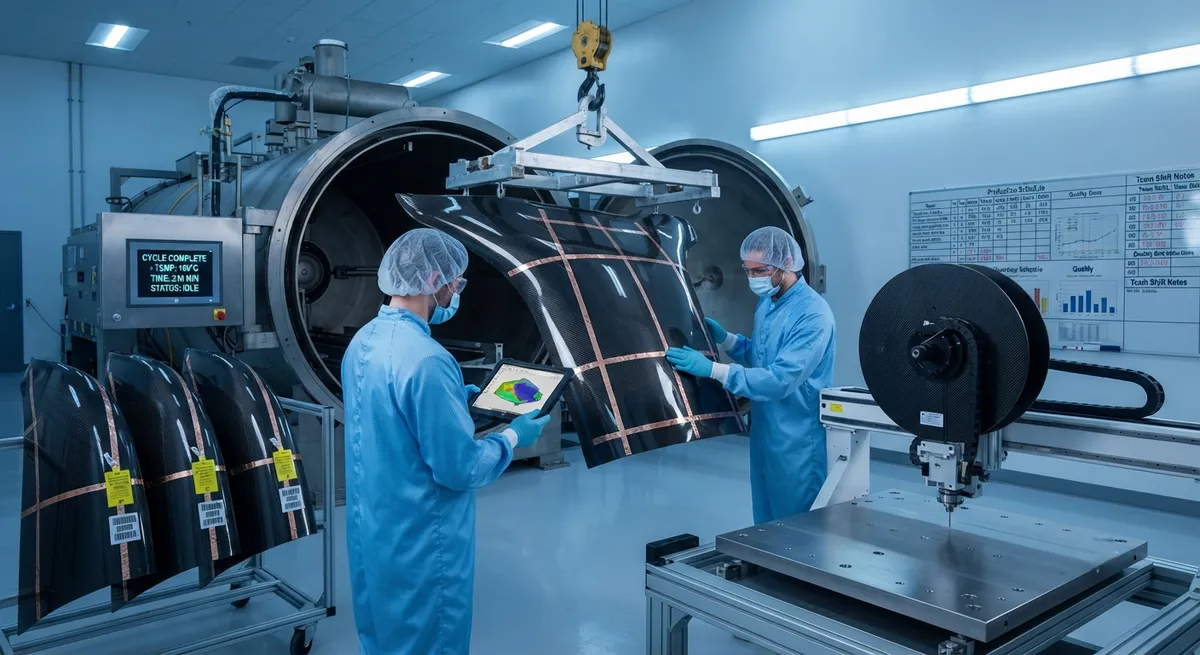
A comprehensive B2B technical analysis of carbon fiber composite engine pylon fairings for commercial aircraft. This article examines aerodynamic shaping requirements, structural load paths, thermal management challenges, lightning strike protection, and manufacturing processes for CFRP pylon fairings used on narrow-body and wide-body aircraft. Includes comparative data on weight savings, drag reduction, and fatigue performance versus traditional aluminum fairings.
Introduction
Engine pylon fairings are the aerodynamic shrouds that enclose the structural pylon connecting an aircraft's engine to the wing. Despite being non-primary-structural components, these fairings play a critical role in aircraft performance: they must maintain smooth airflow over the pylon-wing junction, withstand engine vibration and thermal loads, provide access for maintenance, and protect the pylon structure from environmental exposure. The transition from aluminum to carbon fiber reinforced polymer (CFRP) fairings has become a standard practice on modern commercial aircraft programs, driven by the need for weight reduction, improved fatigue life, and design flexibility for complex aerodynamic contours.
On a typical narrow-body aircraft such as the Airbus A320neo or Boeing 737 MAX, the engine pylon fairing assembly comprises 8–12 individual panel segments, including the forward fairing, aft fairing, side panels, lower bifurcation fairing, and the thrust reverser cowl. The total surface area ranges from 6 to 12 square meters depending on engine size, and the weight of a full CFRP fairing set is approximately 35–55 kg — a 40–55% reduction compared to aluminum equivalents weighing 70–110 kg. On a fleet of 1,000 aircraft operating 3,000 flight cycles per year, this translates to annual fuel savings of approximately 1,200–1,800 metric tons of Jet A-1 fuel per year.
This article provides an engineering examination of the key technical considerations for CFRP engine pylon fairings, including aerodynamic shaping, structural architecture, thermal protection, lightning strike mitigation, manufacturing methods, and an outlook on next-generation developments.
Aerodynamic Design Requirements
The external shape of an engine pylon fairing is governed by conflicting aerodynamic requirements. At the forward section, the fairing must smoothly transition the airflow from the wing lower surface into the engine inlet, minimizing flow separation at high angles of attack. The aft section must manage exhaust gas interaction with the wing flap system, preventing hot gas ingestion and reducing interference drag. Computational fluid dynamics (CFD) optimization of pylon fairing contours has demonstrated drag reductions of 1.5–3.0 drag counts (equivalent to 0.3–0.6% total aircraft drag) compared to baseline designs.
CFRP's formability enables the manufacture of doubly curved surfaces that would be prohibitively expensive to produce in aluminum via stretch forming or machining. The ability to tailor ply orientations locally allows designers to create variable-stiffness panels that maintain aerodynamic shape under aerodynamic pressure loads of up to ±15 kPa while accommodating thermal expansion mismatches with the metallic pylon structure.
| Parameter | Aluminum Alloy (2024-T3) | CFRP (Prepreg, 177°C cure) | Unit |
|---|---|---|---|
| Density | 2.78 | 1.56–1.60 | g/cm³ |
| Total fairing assembly weight (A320-class) | 85–110 | 35–55 | kg |
| Max continuous service temperature | 150 | 177 (wet) / 200 (dry) | °C |
| Thermal conductivity (in-plane) | 120–150 | 2–8 (anisotropic) | W/m·K |
| CTE (coefficient of thermal expansion) | 22.3 | −1.0 to 3.0 (tailored) | ppm/°C |
| Fatigue endurance limit (10⁷ cycles, R=0.1) | 130–160 | 280–400 | MPa |
| Acoustic fatigue life (150 dB SPL) | 2,000–4,000 hours | 10,000–25,000 hours | — |
| Lightning strike damage area (Zone 1A, 200 kA) | 0.5–1.5 cm² erosion | 5–15 cm² (requires protection) | — |
| Manufacturing cycle time per panel | 3–8 hours (forming + machining) | 4–10 hours (layup + cure + trim) | hours |
| Tooling cost per fairing program | $1.5–2.5M | $3.0–6.0M | USD |
Structural Architecture and Load Paths
Engine pylon fairings are classified as secondary structure under FAR/JAR 25.869 and CS-25, meaning their failure does not threaten the aircraft's continued safe operation. However, they must withstand a demanding combination of loads:
- Aerodynamic pressure loads: Steady-state and fluctuating pressures from the high-energy airflow around the pylon-nacelle region, with peak dynamic pressures reaching 8–15 kPa during takeoff and high-speed cruise.
- Engine vibration: Broadband vibration from engine operation, with dominant frequencies between 50–500 Hz and acceleration levels up to 5–15 g RMS at the fan case interface.
- Acoustic loading: High-intensity noise from the engine fan, compressor, and turbine stages, with sound pressure levels (SPL) reaching 150–160 dB in the aft fairing region adjacent to the core engine.
- Thermal loads: Radiant and convective heating from the engine core and exhaust, with surface temperatures on the lower bifurcation fairing reaching 120–180°C during cruise and up to 200°C during reverse thrust operation.
- Ground handling and maintenance loads: Access panel opening/closing cycles (5,000–10,000 cycles over life), engine removal/installation loads, and tool drop impacts.
CFRP fairings typically use a sandwich construction with carbon fiber/epoxy facesheets (0.5–1.5 mm thick per facesheet) bonded to a Nomex or aluminum honeycomb core (6–15 mm thick, 3.2–6.4 mm cell size). The facesheet layup is optimized for the specific load regime of each panel location. Forward fairings are designed with a quasi-isotropic layup (e.g., [45/0/−45/90]ₛ) to handle multi-directional aerodynamic pressures, while aft fairings incorporate additional 0° plies for bending stiffness and ±45° plies for shear resistance in the high-vibration environment near the engine mount.
Thermal Management and Fire Protection
The thermal environment around the engine pylon presents one of the most challenging design requirements for CFRP fairings. Standard epoxy matrix systems are limited to continuous service temperatures of 177°C (wet) and 200°C (dry). In regions where local temperatures exceed these limits, three mitigation strategies are employed:
- Heat shields: Stainless steel (304SS or Inconel 625) or titanium (Ti-6Al-4V) heat shields are mechanically fastened to the interior surface of CFRP panels in high-temperature zones. These shields create a 5–15 mm air gap and reduce the temperature at the composite surface by 50–80°C.
- Thermal barrier coatings: Intumescent coatings or ceramic-based thermal barrier coatings (TBCs) applied to the internal surface of the fairing provide additional 100–200°C of protection for up to 15 minutes during a fire event, meeting the 5-minute fire resistance requirement of CS-25.855 and FAR 25.855.
- High-temperature resin systems: For the most demanding applications, bismaleimide (BMI) or polyimide resin systems can replace standard epoxy. BMI systems (e.g., Cytec 5250-4 or Hexcel HexPly M65) offer continuous service temperatures of 230–250°C, while polyimide systems (PMR-15, AFR-PE-4) extend to 300–350°C at significantly higher material and processing costs.
The lower bifurcation fairing, which passes directly beneath the engine core, is the most thermally critical component. On high-bypass turbofan engines such as the CFM International LEAP-1A or Pratt & Whitney PW1100G, temperatures on this fairing can reach 190–210°C at the core trailing edge during takeoff power settings. Titanium heat shields with multi-layer radiation barriers (3–5 layers of ceramic cloth with reflective aluminum foil interleaving) are typically specified for this panel.
Lightning Strike Protection
Aircraft fairings located within lightning strike Zone 1A (the engine nacelle and pylon leading edge region, as defined by SAE ARP5414) must withstand direct attachment of lightning channels with peak currents up to 200 kA and action integrals of 2×10⁶ A²·s. CFRP's low electrical conductivity (0.1–1.0 S/m through-thickness, compared to 18–23×10⁶ S/m for aluminum) makes it vulnerable to catastrophic damage from lightning attachment, including: composite delamination, resin vaporization, fiber fracture, and loss of structural integrity.
Industry-standard lightning strike protection (LSP) for CFRP pylon fairings includes:
- Expanded copper foil (ECF): A 0.05–0.10 mm thick copper mesh embedded in the outer ply of the composite laminate, typically with an areal weight of 75–200 g/m². The mesh diverts lightning current with a surface resistivity of 0.5–2.0 mΩ/square.
- Aluminum flame spray: A 0.1–0.3 mm thick layer of aluminum applied to the external surface via electric arc or plasma spray. This method provides excellent conductivity (surface resistivity <0.5 mΩ/square) but adds weight and requires additional surface preparation for paint adhesion.
- Interlayer woven wire: Metal wire cloth (copper or aluminum) co-cured between the first and second plies of the laminate. This approach balances conductivity with interlaminar fracture toughness.
Qualification testing per SAE ARP5416 requires CFRP fairing panels to survive multiple simulated lightning strikes without the attachment point penetrating through the panel thickness or causing damage beyond repairable limits. Post-strike inspection is conducted via ultrasonic C-scan and thermography to verify that any delamination does not exceed 25 mm from the attachment point.
Manufacturing Processes
The manufacturing of CFRP engine pylon fairings employs several established processes, each with specific advantages for different panel geometries and production volumes:
- Prepreg autoclave curing: The dominant process for high-performance aerospace fairings. Unidirectional or woven carbon fiber prepreg (epoxy resin content 35–42% by weight) is hand-laid or automated tape-laid (ATL) onto Invar or steel tooling, vacuum-bagged, and cured at 177°C and 6–7 bar pressure for 120–180 minutes. Process yields excellent void content (<1%) and uniform fiber volume fraction (58–62%).
- Resin transfer molding (RTM): Used for smaller, geometrically complex panels such as the forward fairing lip and edge close-outs. Dry carbon fiber preforms are placed in a matched metal mold, and low-viscosity epoxy resin is injected at 2–10 bar pressure. Cycle times of 45–90 minutes are achievable, though tooling costs are 30–50% higher than prepreg tooling.
- Out-of-autoclave (OOA) processing: Prepreg systems formulated for vacuum-bag-only cure (e.g., Cycom 5320 or Hexcel HexPly M56) are increasingly adopted for fairing panels with moderate structural requirements. OOA processing eliminates autoclave capital costs and enables larger panel sizes limited only by oven dimensions. Current OOA systems achieve void contents of 1–3% and fiber volumes of 55–60%.
The global market for aerospace-grade carbon fiber prepreg was valued at approximately $2.8 billion in 2025, with engine nacelle and pylon fairing applications accounting for an estimated 12–15% of this total. Market growth is projected at 8–10% CAGR through 2032, driven by increasing composite content in next-generation narrow-body aircraft and the expansion of aftermarket replacement demand.
Frequently Asked Questions
What is the typical weight reduction when switching from aluminum to CFRP engine pylon fairings?
A CFRP fairing set for a narrow-body aircraft typically weighs 35–55 kg, compared to 85–110 kg for aluminum — a weight reduction of 40–55%. On a wide-body aircraft like the Boeing 787, the saving is proportionally larger due to the greater surface area of the fairing assembly.
How do CFRP fairings handle engine bay fire conditions?
CFRP fairings rely on a combination of intumescent coatings, heat shields (stainless steel or titanium), and fire-resistant resin systems. The assembly must meet the 5-minute fire resistance requirement of CS-25.855 and FAR 25.855, where the internal surface is exposed to a 1,100°C flame and the external surface must not exceed 204°C. Post-fire structural integrity must allow the aircraft to complete its flight and land safely.
What is the service life of a CFRP pylon fairing compared to aluminum?
While aluminum fairings typically require replacement every 8–12 years due to fatigue cracking and corrosion, CFRP fairings have demonstrated service lives exceeding 20 years on programs like the Boeing 777 (which introduced composite pylon fairings in 1995). Acoustic fatigue is the most common life-limiting factor for CFRP fairings, with qualification testing targeting 25,000–50,000 flight cycles without repair.
Can damaged CFRP fairings be repaired in the field?
Yes. Minor damage (delamination <25 mm diameter, impact damage not penetrating the facesheet) can be repaired using wet layup or prepour patch procedures per SRM (Structural Repair Manual) guidelines. Major damage typically requires panel replacement. The repair process requires controlled temperature and humidity conditions, making line maintenance more challenging than with aluminum, where damage can often be stopped-drilled and patched in any environment.
Are CFRP pylon fairings more expensive than aluminum ones?
Initial acquisition cost for CFRP fairings is 50–100% higher than aluminum equivalents, primarily due to material costs ($80–150/kg for aerospace prepreg vs. $10–25/kg for aluminum sheet) and tooling investment. However, lifecycle cost analysis shows CFRP becomes cost-effective at the fleet level when fuel savings ($1.2–1.8M over a 20-year fleet operation), reduced inspection requirements, and longer replacement intervals are factored in. Typical OEM programs achieve breakeven at 3–5 years of in-service operation.
Part of topic
Related Articles
- Carbon Fiber Mooring for Floating Offshore Wind: Fatigue and Corrosion in Deep Water
- Carbon Fiber Bicycle Frame Optimization: Layup Design and Manufacturing for Competitive Racing
- Carbon Fiber CFRP Retrofit for Infrastructure: Bridge and Building Seismic Strengthening
- Carbon Fiber Medical Imaging Equipment: Lightweight Gantry and Couch Structures for MRI/CT
- Carbon Fiber EV Battery Enclosures: Crash Safety and Electromagnetic Shielding Design
- Carbon Fiber Structures for Low-Altitude Economy: UAV Airframes and eVTOL Components
Interested in Our Products?
Contact our team for competitive pricing and technical specifications.
Get a QuoteRelated Products

Carbon fiber standard plate-3k stripe
Lightweight, ultra-rigid standard sheets for drone fuselages, robot housings, facades and structural applications.

Carbon Fiber Plate — 3K Twill T700 3.0mm
Medium-thickness 3.0mm carbon fiber plate offering significantly higher load capacity while maintaining attractive 3K twill finish. Suitable for structural brackets, reinforcement plates, and load-bearing panels.

Carbon Fiber Plate — 3K Twill T700 1.5mm
Thin 1.5mm carbon fiber plate with 3K twill weave surface. Lightweight and stiff, commonly used for covers, panels, drone bodies, and applications requiring a premium aesthetic appearance.

Square Carbon Fiber Tube — 3K Twill T700
Square cross-section carbon fiber tube manufactured with 3K twill weave for torsional strength. Preferred for structural frames, trusses, and support columns where rectangular geometry offers design flexibility.

Carbon Fiber Plate — UD Unidirectional T700
Unidirectional carbon fiber plate with all fibers oriented in a single direction for maximum strength along the fiber axis. Essential for structural reinforcements, splints, and applications where load direction is predictable.