
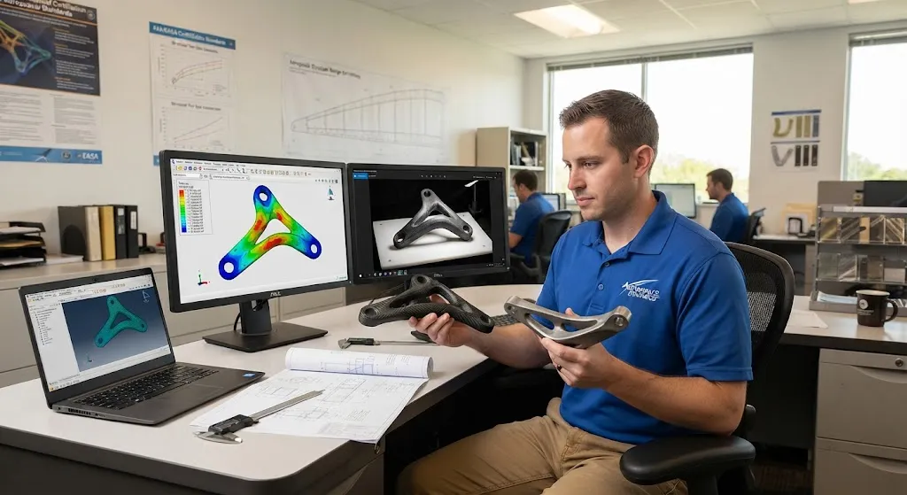
Aerospace structural brackets represent one of the most promising applications for combining topology optimization with carbon fiber reinforced polymer (CFRP) composites. These components — wing-to-fuselage attachments, engine mount brackets, seat rail fittings, and avionics bay support
Introduction
Aerospace structural brackets represent one of the most promising applications for combining topology optimization with carbon fiber reinforced polymer (CFRP) composites. These components — wing-to-fuselage attachments, engine mount brackets, seat rail fittings, and avionics bay supports — are traditionally machined from titanium or aluminum billets, producing parts that are 60-80% heavier than structurally necessary because machining constraints force uniform wall thicknesses and conventional geometries. Topology optimization software removes this constraint by algorithmically distributing material only where stress paths require it, producing organic, load-following shapes that are impossible to manufacture in metal but perfectly suited to composite fabrication.
For aerospace weight engineers, the combination is transformative: topology optimization identifies the minimum material needed to carry flight loads with appropriate safety factors, and CFRP manufacturing — particularly automated fiber placement (AFP) and resin transfer molding (RTM) — can produce these complex geometries with precise fiber orientation that matches the optimized stress field. The result is brackets that weigh 50-70% less than their machined titanium equivalents while meeting all structural, fatigue, and damage tolerance requirements. This article explains the computational methods, manufacturing processes, and certification pathway for topology-optimized CFRP brackets in commercial aircraft.
Topology Optimization Methods for Composite Brackets
Topology optimization for CFRP brackets differs fundamentally from metal optimization because the software must account for anisotropic material behavior, fiber placement constraints, and manufacturing limitations that do not apply to isotropic metals:
| Optimization Parameter | Metal Bracket (Titanium) | CFRP Bracket (Topology-Optimized) |
|---|---|---|
| Material model | Isotropic (E = 110 GPa, ν = 0.34) | Orthotropic (E₁ = 135 GPa, E₂ = 10 GPa, G₁₂ = 5 GPa) |
| Design variables | Density per element (0-1) | Density + fiber orientation (0°, ±45°, 90°) per element |
| Manufacturing constraints | Minimum wall thickness, draft angle | Fiber continuity, minimum bend radius, tool access |
| Failure criteria | Von Mises stress < yield strength | Tsai-Wu or Hashin criteria (fiber/matrix failure modes) |
| Typical weight reduction | — | 50-70% vs machined titanium |
The optimization process uses finite element analysis with SIMP (Solid Isotropic Material with Penalization) or level-set methods, iterating until convergence on a design that satisfies all load cases with minimum volume. The output is a 3D geometry that must then be translated into a manufacturable composite layup — this is where the design-manufacturing integration becomes critical.
Manufacturing Topology-Optimized CFRP Brackets
Three manufacturing routes are used to produce topology-optimized CFRP brackets, each suited to different production volumes and geometric complexity:
- Automated fiber placement (AFP): Robotic fiber placement heads deposit towpreg (pre-impregnated carbon fiber tows) onto a mandrel or mold, following the optimized fiber orientation paths. AFP is ideal for medium-complexity brackets with gentle curvature, producing parts with 55-62% fiber volume fraction and fiber orientations that precisely match the stress field. Cycle time is 2-4 hours per bracket.
- Resin transfer molding (RTM): Dry fiber preforms are placed in matched metal molds and injected with fast-cure epoxy resin. RTM handles higher geometric complexity than AFP, including internal channels and undercuts, with cycle times of 1-3 hours. This is the preferred route for brackets requiring high dimensional accuracy and surface finish.
- 3D-printed composite molds: For low-volume or prototype brackets, 3D-printed (SLA or SLS) mandrels and molds enable rapid iteration of topology-optimized geometries. The composite bracket is hand layup or vacuum-bagged on the 3D-printed tool, with cure in an oven rather than autoclave. This approach reduces lead time from 12-16 weeks to 2-4 weeks for first-article parts.
Performance Comparison: CFRP vs Titanium Brackets
The structural advantages of topology-optimized CFRP brackets become quantifiable when comparing equivalent designs for a typical aerospace fitting application:
| Parameter | Titanium Bracket (Machined) | CFRP Bracket (Topology-Optimized) | Improvement |
|---|---|---|---|
| Part mass | 2.8-3.5 kg | 0.9-1.4 kg | 50-70% reduction |
| Static strength margin | 1.5x design ultimate load | 1.5x design ultimate load | Equivalent |
| Fatigue life (10⁷ cycles) | No crack initiation | No delamination growth | Equivalent |
| Cost per bracket | $4,500-8,000 | $3,200-6,500 | 15-30% lower |
| Lead time | 16-24 weeks | 8-14 weeks | 40-50% faster |
| Material utilization | 15-25% (billet to part) | 70-85% (preform to part) | Higher efficiency |
The cost advantage is driven by two factors: elimination of titanium billet machining waste (85% of billet mass is removed as chips) and reduced tooling complexity for composite molds compared to multi-axis CNC machining fixtures. At production volumes above 200 brackets per year, CFRP achieves clear cost superiority.
Certification Pathway for Flight-Critical CFRP Brackets
The certification of topology-optimized CFRP brackets follows a structured pathway defined by FAA (14 CFR Part 25) and EASA (CS-25) regulations:
- Design data package: Complete finite element analysis with load justification, material allowable data (CMH-17 or equivalent), and damage tolerance analysis demonstrating compliance with FAR 25.571.
- Material qualification: Environmental conditioning (hot/wet, cold/dry), static mechanical testing per ASTM D30, and fatigue testing per ASTM D3479 to establish material allowables for the specific layup and cure cycle.
- Component testing: Static proof load testing to 1.5x design ultimate load, fatigue testing to 2x design service life (40,000 flight hours), and damage tolerance testing with artificial defects (drilled holes, saw cuts) to demonstrate residual strength.
- Production process validation: First article inspection (FAI) per AS9102, process capability studies for fiber volume fraction and void content, and destructive testing of production specimens.
Case Study: Wing-to-Fuselage Bracket Optimization
A recent commercial aircraft program demonstrated the practical benefits of topology-optimized CFRP brackets through a wing-to-fuselage attachment fitting. The original titanium bracket weighed 3.2 kg and required 18 hours of 5-axis CNC machining from a 15 kg billet. The topology-optimized CFRP replacement weighs 1.1 kg — a 66% reduction — and is produced by RTM in a 2.5-hour cycle. The bracket carries 45 kN of design ultimate load with a 1.5x safety factor, meets fatigue requirements for 80,000 flight hours, and passed bird-strike damage tolerance testing with drilled holes up to 6 mm diameter. The total program savings exceed $2.4 million across 800 aircraft, with an additional 12 tonnes of fuel savings over the fleet's 25-year service life.
Frequently Asked Questions
How does topology optimization handle multiple load cases for aerospace brackets?
Modern topology optimization software evaluates dozens of load cases simultaneously — flight maneuvers (2.5g pull-up, 1g cruise), landing impacts (3g vertical, 1g forward), ground taxi, and emergency deceleration — and optimizes the material distribution to satisfy all cases with minimum volume. The software uses weighted compliance objectives or constraint-based optimization where each load case contributes to the final density field. Aerospace brackets typically require 20-40 load cases to cover the full flight envelope, and the optimization converges to a single geometry that handles all conditions efficiently.
What are the main risks in certifying topology-optimized CFRP brackets?
The primary certification risks are: (1) anisotropic behavior requiring extensive material testing across fiber orientations, (2) complex geometry making inspection access difficult for conventional NDT methods, (3) manufacturing variability in fiber placement affecting local properties, and (4) damage tolerance characterization requiring testing of the specific topology rather than generic coupon data. These risks are mitigated through design-of-experiments testing, expanded NDT protocols (CT scanning for first articles), and statistical process control in manufacturing.
Can topology-optimized CFRP brackets be modified after certification?
Any geometric modification to a certified bracket requires re-analysis and potentially re-testing to maintain type certification. Minor changes (surface finish, mounting hole tolerance) can be covered by engineering order without re-certification, but changes to load paths, thickness, or fiber orientation require updated stress analysis and may trigger additional component testing. The certification documentation package must be maintained throughout the bracket's service life, with modification records tracked through the engineering change process.
Conclusion
Topology optimization combined with CFRP manufacturing represents the convergence of computational design and advanced materials science in aerospace structural engineering. The 50-70% weight reduction, 15-30% cost advantage, and 40-50% faster production compared to machined titanium brackets make this approach the clear choice for new aircraft programs targeting maximum fuel efficiency. As computational tools mature and manufacturing processes scale, topology-optimized CFRP brackets will expand from wing and engine applications to interior structures, landing gear components, and satellite hardware.
For aerospace engineers evaluating topology optimization for bracket applications, success requires tight integration between structural analysis, materials engineering, and manufacturing process development. Explore our aerospace-grade carbon fiber materials, including prepreg systems and dry fiber preforms suitable for topology-optimized bracket manufacturing, or contact our engineering team to discuss design support for your aerospace structural program.
Part of topic
Related Articles
- Bio-Based Carbon Fiber Precursors: Lignin and Polyethylene for Low-Cost Production
- Large-Tow Carbon Fiber Cost Analysis: 48K vs 60K Price-Performance Comparison
- Carbon Fiber-Resin Interface Bonding: Surface Treatment and Coupling Agent Optimization
- Digital Twin for Carbon Fiber Manufacturing: Real-Time Process Monitoring and Defect Prevention
- Thermoplastic Carbon Fiber Welding for Automotive: Ultrasonic and Induction Welding Process Windows
- Large-Tow Carbon Fiber Wet Spinning: Process Optimization for 48K/60K Production Efficiency
Interested in Our Products?
Contact our team for competitive pricing and technical specifications.
Get a QuoteRelated Products

Round Carbon Fiber Tube — UD Unidirectional T700
Unidirectional (UD) round tube with all fibers aligned axially for maximum longitudinal stiffness. Ideal for applications requiring high bending rigidity with minimal weight, such as shafts, struts, and structural reinforcements.
Carbon Fiber Drone Arm
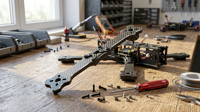
Precision-molded carbon fiber drone arm combining unidirectional fiber for stiffness and woven layers for torsional strength. Designed for FPV, photography, and industrial drone platforms. Each arm is CNC-machined to exact specifications.

Custom Carbon Fiber Medical Device Components
Medical-grade carbon fiber components manufactured for imaging equipment, surgical instruments, and patient support systems. Carbon fiber's radiolucency (X-ray transparency) and high strength-to-weight ratio make it ideal for CT scanner beds, wheelchair frames, surgical robot arms, and MRI-compatible accessories. Biocompatible resin systems available.
Custom Carbon Fiber Sports Protective Gear Components
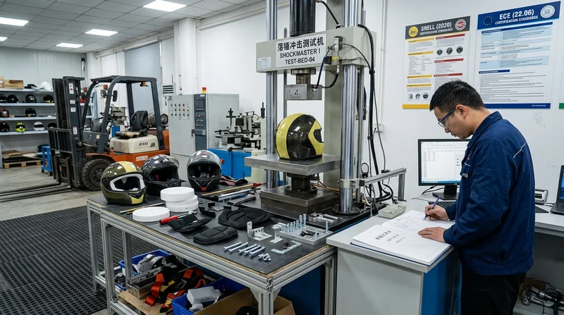
High-impact carbon fiber components for protective sports gear. Our multi-layer carbon/Kevlar hybrid layups provide superior impact resistance while keeping weight minimal. Used in motorcycle helmet shells, knee brace frames, chest protectors, and shin guard inserts. EPS foam integration available for complete helmet shell manufacturing.
Custom Carbon Fiber Drone Arm — Lightweight & Vibration-Damping
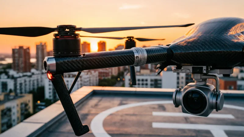
High-modulus carbon fiber drone arms designed for industrial, agricultural, and surveying UAVs. Replace heavy aluminum arms with our custom-molded CFRP arms — 40-60% lighter with superior vibration damping for stable flight and sharper imaging.