
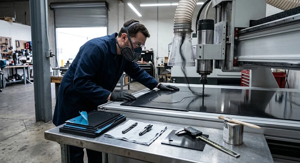
Carbon fiber sheet machining is the discipline that turns a cured CFRP plate into a dimensioned part — routed profiles, drilled hole patterns, milled pockets and finished edges — without delaminating plies, burning the matrix or burying the shop in conductive dust. Unlike metal machining, every para
Introduction
Carbon fiber sheet machining is the discipline that turns a cured CFRP plate into a dimensioned part — routed profiles, drilled hole patterns, milled pockets and finished edges — without delaminating plies, burning the matrix or burying the shop in conductive dust. Unlike metal machining, every parameter here is a compromise between three enemies: abrasive fibers that dull cutters, a polymer matrix that softens under heat, and a laminated structure that wants to split at the exit of every hole. This article explains how carbon fiber sheet cutting and carbon fiber plate cutting differ by process, which tolerances are realistic across carbon fiber sheet thickness classes, and what tooling and parameters separate a clean edge from a scrapped plate.
For buyers and engineers, the practical takeaway is simple: the process you choose at quotation time fixes the tolerance band, the edge quality and the cost. Choosing after the parts arrive is not an option.
Why Carbon Fiber Sheet Machining Behaves Differently from Metal
Three material properties drive every decision on the machine:
- Abrasion: carbon fibers score carbide like sandpaper. Uncoated end mills that machine aluminum all day can lose 0.1 mm of diameter within a few meters of cut in CFRP, silently destroying hole tolerance.
- Low thermal ceiling: epoxy matrices begin to lose stiffness above 80-120 °C. A dull bit or aggressive feed converts cutting energy into heat, and the matrix around the cut turns powdery or charred — a defect that no post-process can repair.
- Laminated structure: each ply is strong in its own plane but weakly bonded to the next. Down-cut, up-cut and compression geometries exist specifically to keep those plies pressed together at the entry and exit of the cut.
Add the health and equipment hazard — carbon dust is conductive and abrasive to machine ways — and it becomes clear why carbon fiber sheet machining demands dedicated extraction, dedicated tooling policies and parameter discipline that a mixed-use job shop rarely maintains.
Carbon Fiber Sheet Cutting: Process Options and Trade-offs
Four processes cover almost all production carbon fiber sheet cutting work. The right choice depends on part geometry, edge requirement and batch size:
| Process | Typical kerf / tolerance | Edge quality | Heat input | Best for |
|---|---|---|---|---|
| CNC routing (compression bits) | 2-3 mm kerf, ±0.1 mm positional | Very good both faces with compression geometry | Low if parameters held | Profiles, pockets, hole patterns, most production work |
| Abrasive waterjet | 0.8-1.2 mm kerf, ±0.15 mm | Rough taper on thick plate; fiber pull-out at exit | None | Thick plate, complex outlines, no-dust environments |
| Ultrasonic cutting | 0.3-0.5 mm kerf, ±0.05 mm | Excellent, minimal delamination | Very low | Thin sheet, precision gaskets, cleanroom parts |
| CO₂ laser | Not recommended | Charred matrix, heavy delamination | Extreme | Avoid for structural CFRP; resin burns before it cuts |
CNC routing remains the workhorse for carbon fiber plate cutting because it combines dimensional control, reusable fixtures and a capital cost a workshop can justify. Waterjet earns its place where the outline is too complex for a 3-6 mm router bit or where the plate is too thick for a single-pass route. Laser stays off the table: epoxy is flammable, the kerf is a heat-affected zone, and the fume alone disqualifies it.
Carbon Fiber Sheet Machining: Tolerances by Thickness
Realistic tolerances shift with carbon fiber sheet thickness because thinner stock flexes under clamping and thicker stock loads the cutter laterally. Numbers below assume quasi-isotropic plate, vacuum or spoilboard fixturing, and a calibrated 3-axis router:
| Sheet thickness | Thickness tolerance (quality grade) | Profile positional tolerance | Hole diameter tolerance | Machining note |
|---|---|---|---|---|
| 0.5-1 mm | ±0.05 mm | ±0.08 mm | ±0.05 mm | Ultrasonic or nested routing on sacrificial layer; vacuum alone rarely holds |
| 2-3 mm | ±0.1 mm | ±0.1 mm | ±0.08 mm | Compression bit, full vacuum table, step-down passes |
| 4-6 mm | ±0.15 mm | ±0.12 mm | ±0.1 mm | Peck drilling mandatory; multiple passes to final depth |
| 8-12 mm | ±0.2 mm | ±0.15 mm | ±0.12 mm | Waterjet often cheaper; router needs rigid setup and reduced feed |
These bands are achievable, not automatic. Shops that quote ±0.05 mm on a 10 mm plate are either planning a secondary grinding operation or planning to disappoint you. When a drawing calls tighter than the table allows, ask what the verification method is — CMM after machining, or calipers at the bench.
Tooling and Parameters for Carbon Fiber Plate Cutting
Tooling is where carbon fiber plate cutting is won or lost. Policy that holds up in production:
- Compression bits for routing: up-cut and down-cut flutes combined keep both faces of the laminate sealed during the cut. Uncoated solid carbide for short runs; diamond-like carbon (DLC) or diamond-coated tooling for series work, where tool life multiplies 10-20x against uncoated.
- Speeds and feeds: surface speed 150-250 m/min with carbide, feed per tooth 0.03-0.06 mm. High RPM with low feed burns the matrix; low RPM with heavy feed lifts plies. The sound of the cut tells you more than the calculator: a scream means rub, a growl means bite.
- Drilling: step drills or dagger-point carbide, peck cycles every 2-3 mm, sacrificial backing under the exit face. One continuous plunge through 6 mm plate is how exit delamination gets born.
- Extraction: dust extraction at the spindle plus a vacuum table. Conductive carbon dust finds its way into servo encoders and electrical cabinets; shops that skip extraction pay for it in machine downtime.
- Edge finishing: seal machined edges with thin cyanoacrylate or epoxy if the part will see handling or moisture; sanding alone leaves open fiber ends that wick and abrade.
Fixture discipline rounds out the list: spoilboard fresh enough to seal, clamping that does not point-load thin sheet, and a cut sequence that leaves tabs until the final pass so the offcut does not grab the bit.
Frequently Asked Questions
Can carbon fiber sheets be machined with standard woodworking tools?
A woodworking router can cut thin carbon fiber sheet in a pinch, but three problems appear immediately: no dust extraction rated for conductive abrasive dust, no compression tooling, and no rigidity for consistent tolerances. Parts that are decorative and non-structural may survive the experiment; anything load-bearing or dimensioned should go to a shop with CFRP-specific extraction and tooling policy.
Why does the edge of my machined carbon fiber plate look fuzzy or whitish?
A fuzzy or whitish edge is almost always matrix-starved cutting: the tool rubbed instead of cut, heating the epoxy until it powdered and left fibers free-standing. Causes are a dull bit, feed too low for the RPM, or missing compression geometry. The fix is a sharp compression bit, re-balanced feeds and speeds, and a finishing pass at reduced depth — not more pressure.
Is waterjet or CNC routing better for carbon fiber plate cutting?
Neither is universally better. Routing wins on positional tolerance, hole quality and edge finish on plate up to about 8 mm, and it integrates pockets and drills in one setup. Waterjet wins on complex outlines, thick plate and shops that must avoid airborne dust. Many production runs use waterjet for the blank and CNC routing for the features — the combination that usually costs least per good part.
Conclusion
Carbon fiber sheet machining is a process-selection problem before it is a cutting problem: routing, waterjet and ultrasonic each occupy a different corner of the tolerance-versus-cost space, and laser has no place in structural CFRP. Across carbon fiber sheet thickness classes, quality-grade tolerances run from ±0.05 mm on thin stock to ±0.2 mm on heavy plate — a band that tooling choice, extraction discipline and fixture design either protect or destroy. YongXian supplies CNC-machined carbon fiber sheets and plates cut to drawing, with edge sealing, sealed hole patterns and inspection data available on request. Browse our carbon fiber sheet range or contact our engineering team with your drawing for a machining feasibility review.
Part of topic
Related Articles
- Carbon Fiber Sheets 1/4 Thick: 1/4 Inch Plate Guide
- Filament Wound Epoxy Tubes Disadvantages: Limitations and Failure Modes
- Carbon Fiber K Rating: Security Laminate Grades
- Carbon Fiber Solid Rod: Properties and Applications
- Carbon Fiber Plate Density: What to Expect from Laminates
- Carbon Fiber Plate 4mm: Stiffness, Machining and Applications
Interested in Our Products?
Contact our team for competitive pricing and technical specifications.
Get a QuoteRelated Products

Carbon Fiber Plate — 3K Twill T700 1.5mm
Thin 1.5mm carbon fiber plate with 3K twill weave surface. Lightweight and stiff, commonly used for covers, panels, drone bodies, and applications requiring a premium aesthetic appearance.

Carbon Fiber Plate — 3K Twill T700 3.0mm
Medium-thickness 3.0mm carbon fiber plate offering significantly higher load capacity while maintaining attractive 3K twill finish. Suitable for structural brackets, reinforcement plates, and load-bearing panels.
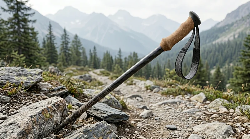
Carbon Fiber Trekking Pole
Lightweight carbon fiber trekking pole manufactured from high-grade carbon fiber tube. Weighs only 160g per pole while providing superior shock absorption and durability for hiking, trail running, and backpacking.

Square Carbon Fiber Tube — 3K Twill T700
Square cross-section carbon fiber tube manufactured with 3K twill weave for torsional strength. Preferred for structural frames, trusses, and support columns where rectangular geometry offers design flexibility.
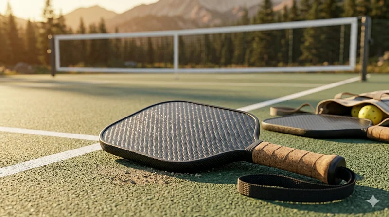
Carbon Fiber Pickleball Paddle
High-performance pickleball paddle with Toray T700 carbon fiber face and polypropylene honeycomb core. Delivers excellent power-to-weight ratio, spin generation, and vibration dampening for competitive play.