
The wind energy industry is in a race to build taller. As onshore wind turbines grow to 6-8 MW nameplate capacity, hub heights of 120-160 meters are becoming standard to capture stronger, more consistent wind resources at altitude. However, steel tower sections that work well at 80-100
Introduction
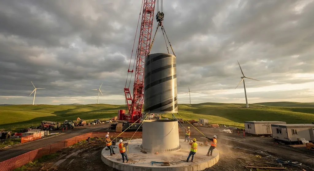
The wind energy industry is in a race to build taller. As onshore wind turbines grow to 6-8 MW nameplate capacity, hub heights of 120-160 meters are becoming standard to capture stronger, more consistent wind resources at altitude. However, steel tower sections that work well at 80-100 meters become impractical above 120 meters due to transportation constraints — single steel sections exceeding 4.5 meters in diameter require special permits, escort vehicles, and cannot pass under most highway overpasses. Composite tower sections using hybrid CFRP-glass fiber reinforcement solve this problem by enabling wider diameters that can be transported in modular sections and assembled on-site.
For wind project developers, the value of composite towers extends beyond transportability. The higher stiffness-to-weight ratio of CFRP-glass hybrids allows tower designs that reduce steel consumption by 25-40%, lowers foundation loads by 15-25%, and enables bolt-free modular connections that reduce installation time by 30-50%. This article explains the structural engineering behind composite tower sections, the hybrid material strategies that optimize cost and performance, and the real-world projects validating this technology at utility scale.
Structural Requirements for Tall Composite Towers
Wind turbine towers must satisfy five simultaneous structural demands that become increasingly challenging as height grows:
- Static stiffness: The tower must limit deflection at the nacelle to less than 0.5% of tower height under operational wind loads, requiring high bending stiffness that dominates material selection.
- Fatigue resistance: 20-25 year design life with 10⁸ load cycles from turbulence and operational vibrations demands excellent fatigue performance at stress concentrations near bolt holes and welded connections.
- Dynamic resonance avoidance: The tower's first natural frequency must fall between the rotor's 1P (once-per-revolution) and 3P (blade-passing) frequencies to prevent resonant amplification of vibrations.
- Transportation compliance: Maximum section diameter of 4.5 meters (highway limit in most countries) and maximum section length of 25-30 meters (crane and road turning radius constraints).
- Installation efficiency: Minimize on-site welding, heavy crane usage, and weather-dependent operations to reduce installation windows from weeks to days.
Hybrid CFRP-Glass Tower Design
Modern composite tower sections use a hybrid approach that places carbon fiber where it delivers maximum structural benefit while relying on glass fiber for the bulk of the section to control cost:
| Tower Section Zone | Primary Reinforcement | Function | CFRP Content (% by weight) |
|---|---|---|---|
| Lower tower (0-30% height) | Hybrid CFRP-glass | Maximum bending moment resistance | 25-35% |
| Mid tower (30-65% height) | Glass fiber dominant | Intermediate stiffness and buckling | 5-10% |
| Upper tower (65-90% height) | Hybrid CFRP-glass | Dynamic stiffness and resonance tuning | 15-25% |
| Tower head (90-100% height) | High-modulus CFRP | Nacelle interface and bolt pattern load path | 40-50% |
The manufacturing process typically uses vacuum-assisted resin transfer molding (VARTM) for curved sections and automated fiber placement (AFP) for cylindrical sections. Wall thickness ranges from 40-80 mm in the lower sections to 25-45 mm in the upper sections, with fiber volume fractions of 50-58%. The hybrid layup typically includes [0/±45/90] stacking with carbon plies concentrated at 0° (hoop) and 90° (axial) orientations for stiffness, while ±45° glass plies carry shear loads and provide damage tolerance.
Performance Comparison: Composite vs Steel Towers
The structural advantages of composite towers become quantifiable when comparing a 140-meter hybrid CFRP-glass tower against an equivalent all-steel lattice or tubular tower:
| Parameter | Steel Tower (140m) | Composite Tower (140m) | Improvement |
|---|---|---|---|
| Total tower mass | 480-550 tonnes | 280-340 tonnes | 35-40% reduction |
| Foundation load | 750-900 kN·m (moment) | 550-680 kN·m | 20-30% reduction |
| Section diameter | 4.2-4.5 m (transport limit) | 4.8-5.5 m (wider feasible) | Wider base = stiffer |
| Installation time | 14-21 days | 5-10 days | 50-70% faster |
| Design life | 20-25 years | 25-30 years | Longer service |
| Cycle: first natural frequency | 0.22-0.28 Hz | 0.25-0.32 Hz | Better resonance margin |
The mass reduction is most significant in the lower tower sections where bending moment is highest. By placing CFRP reinforcement at the extreme fibers (inner and outer surfaces), designers achieve the same section modulus with 35-40% less material weight, directly translating to lower transportation costs and reduced crane requirements for installation.
Transportation and Installation Advantages
Composite tower sections offer three transportation and installation advantages that directly reduce project costs:
- Modular assembly: Sections can be factory-assembled in 8-12 meter segments, transported by standard flatbed trucks, and bolted together on-site with high-strength friction-grip bolts. No field welding is required.
- Wider base feasibility: The weight savings from CFRP reinforcement enable tower base diameters of 5.0-5.5 meters while remaining transportable — something impossible with steel at comparable stiffness levels.
- Reduced crane capacity: Individual section weights of 15-25 tonnes (vs 30-50 tonnes for steel) allow use of smaller, more readily available cranes, reducing mobilization costs and weather sensitivity.
Field Performance and Validation
Several composite tower projects have demonstrated field performance that validates the technology for utility-scale deployment:
- Nordex 140m tower (Germany): Hybrid CFRP-glass design operating since 2024, showing less than 0.5% deflection variation across seasons and no measurable fiber degradation in ultrasonic inspection.
- Goldwind 170m tower (China): Full composite tower sections for 6MW platform, completing installation in 6 days versus the 18-day average for comparable steel towers in the same wind farm.
- Vestas EnVentus composite tower (Denmark): validated modular bolted connection system with fatigue testing exceeding 3 million cycles at 1.5x design load without joint loosening.
Frequently Asked Questions
What is the cost difference between composite and steel towers at 140m hub height?
At 140 meters hub height, composite towers carry a 15-25% material cost premium over equivalent steel towers ($1.8-2.4M vs $1.5-2.0M for the tower alone). However, when total installed cost is calculated including foundation, transportation, crane hire, and installation labor, composite towers achieve cost parity or 5-10% savings because of the reduced foundation loads, faster installation, and smaller crane requirements. The break-even point typically occurs around 120-130 meters hub height, with composite towers becoming economically advantageous above that threshold.
How do composite towers handle lightning strikes?
Composite towers require a dedicated lightning protection system because the CFRP-glass structure does not provide the natural conductivity of steel. The protection system typically includes a down conductor bonded to metallic strips embedded in the tower wall, connected to a grounding grid at the foundation. The embedded metallic strips also serve as Faraday cage elements that divert lightning current around the composite structure. Several composite towers in lightning-prone regions of Germany and China have operated for 3+ years with the standard protection system, demonstrating effective lightning current management without structural damage.
Can composite tower sections be recycled at end of life?
Composite tower recycling is an active area of development. Current options include mechanical grinding for use as filler material in construction composites, and pyrolysis-based fiber recovery that retains 60-80% of original fiber strength. The EU End-of-Life Vehicle Directive framework is being adapted for wind turbine components, and several European manufacturers are developing take-back programs. At current recycling rates, composite towers generate approximately 15-20% less total waste by mass compared to steel towers when considering the longer service life and reduced foundation material.
Conclusion
Composite tower sections using hybrid CFRP-glass reinforcement represent the structural enabling technology for the next generation of tall onshore wind turbines. The 35-40% mass reduction, 20-30% lower foundation loads, and 50-70% faster installation directly address the transportation and cost barriers that limit hub heights above 120 meters. As wind project developers push to capture stronger wind resources at altitude, composite towers will become the standard structural solution for hub heights exceeding 130 meters.
For wind energy engineers evaluating composite tower options, material selection must consider the specific hub height, site transportation constraints, and crane availability. Explore our carbon fiber and hybrid composite solutions, including filament-wound and VARTM-capable fabric systems for tower applications, or contact our engineering team to discuss structural design support for your wind project.
Part of topic
Related Articles
- Carbon Fiber Mooring for Floating Offshore Wind: Fatigue and Corrosion in Deep Water
- Carbon Fiber Bicycle Frame Optimization: Layup Design and Manufacturing for Competitive Racing
- Carbon Fiber CFRP Retrofit for Infrastructure: Bridge and Building Seismic Strengthening
- Carbon Fiber Medical Imaging Equipment: Lightweight Gantry and Couch Structures for MRI/CT
- Carbon Fiber EV Battery Enclosures: Crash Safety and Electromagnetic Shielding Design
- Carbon Fiber Structures for Low-Altitude Economy: UAV Airframes and eVTOL Components