
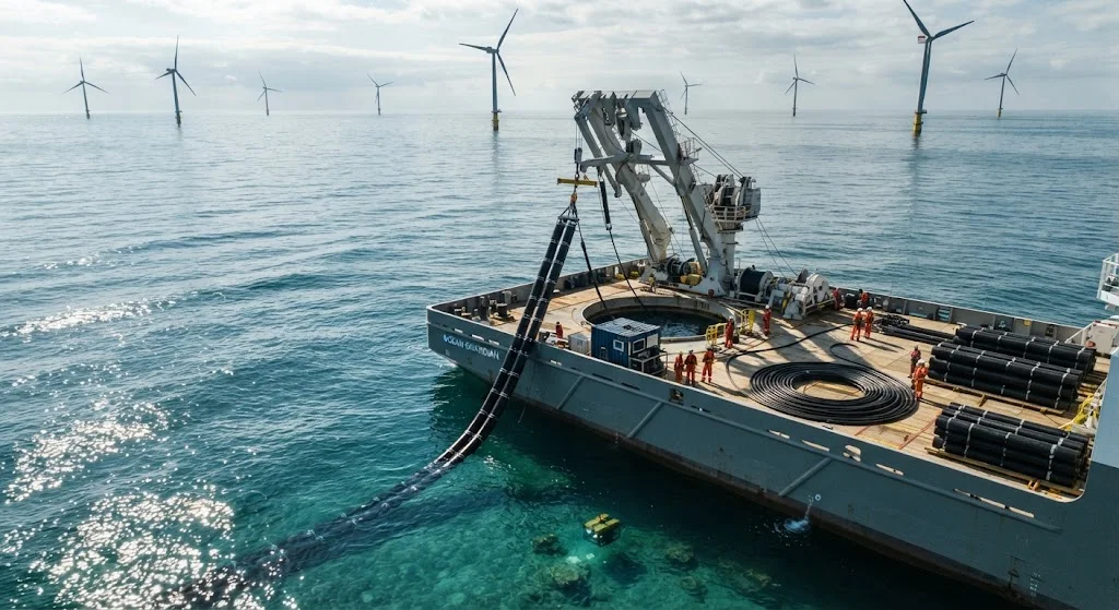
Offshore wind farm cable management represents one of the most challenging infrastructure problems in renewable energy. Subsea power cables connecting turbines to substations and shore face continuous threats from corrosion, mechanical damage during installation, fishing trawler activit
Introduction
Offshore wind farm cable management represents one of the most challenging infrastructure problems in renewable energy. Subsea power cables connecting turbines to substations and shore face continuous threats from corrosion, mechanical damage during installation, fishing trawler activity, anchor drops, and seabed movement. Traditional cable protection systems using steel pipes, concrete mattresses, and rock dumping have served the industry for decades, but their limitations are becoming increasingly apparent as wind farms move into deeper waters, harsher environments, and more complex seabed conditions. Carbon fiber reinforced polymer (CFRP) structures offer a transformative alternative, combining exceptional corrosion resistance with lighter weight and longer service life.
This article examines how CFRP technology is being applied to wind farm cable protection, comparing material performance, installation economics, and lifecycle costs against conventional approaches. For wind farm developers, cable system engineers, and marine infrastructure planners, the data presented here provides a foundation for evaluating CFRP's role in next-generation cable management strategies.
Cable Protection Requirements and Challenges
Subsea cable protection must address multiple simultaneous threats while maintaining cable functionality over a 25-30 year design life. The primary requirements include:
- Mechanical protection: Resistance to impact from dropped objects, trawl board contact, and anchor strikes. The protection system must absorb energy without damaging the cable's conductor, insulation, or armor layers.
- Corrosion resistance: Continuous exposure to saltwater with varying temperatures, pH levels, and biological activity. Steel components require cathodic protection and still face degradation over time.
- Hydrodynamic stability: The protection structure must remain in place despite currents, waves, and seabed scouring. Weight and geometry determine stability, but excessive weight increases installation costs.
- Cable bend radius control: Protection systems must prevent the cable from exceeding its minimum bend radius at touchdown points, J-tube exits, and along the protected route.
- Thermal management: Power cables generate heat during operation. Protection structures must allow adequate heat dissipation to prevent conductor overheating and insulation degradation.
Traditional solutions address these requirements through mass (concrete mattresses), material strength (steel pipes), or volume (rock dumping), but each approach introduces compromises that CFRP can resolve.
CFRP Cable Protection System Design
CFRP cable protection systems leverage the material's unique properties to create structures that outperform traditional alternatives across multiple parameters:
| Parameter | CFRP Protection | Steel Pipe | Concrete Mattress | Rock Dump |
|---|---|---|---|---|
| Weight in water (kg/m) | 15-25 | 80-120 | 200-400 | Variable (bedding dependent) |
| Corrosion rate (mm/year) | 0 (no corrosion) | 0.05-0.15 (with CP) | Surface degradation | N/A |
| Design life (years) | 50+ | 25-30 (with maintenance) | 25-30 | Indefinite (but settlement) |
| Impact energy absorption (kJ) | 15-25 | 20-30 | 30-50 | Passive (distributed) |
| Installation vessel requirement | Light DP vessel | Heavy lift vessel | Heavy lift vessel | Rock dumping vessel |
| Installation rate (m/day) | 500-1000 | 200-400 | 100-200 | Variable (weather dependent) |
| Cable heat dissipation | Excellent (low thermal resistance) | Moderate (steel conducts) | Poor (concrete insulates) | Moderate |
| Fishing gear interaction | Gear slides off (smooth surface) | Gear catches on joints | Gear catches on edges | Gear becomes embedded |
The key CFRP advantages are weight reduction (80-95% lighter than alternatives), elimination of corrosion, and faster installation. A CFRP protection structure weighing 20 kg/m provides the same mechanical protection as a steel pipe weighing 100 kg/m, while the CFRP system requires no cathodic protection, no corrosion monitoring, and no maintenance dives over its service life.
Installation Advantages
CFRP cable protection systems transform installation economics through three mechanisms:
- Vessel requirements: CFRP structures' light weight enables installation from smaller, dynamically positioned (DP) vessels rather than expensive heavy-lift crane barges. Daily vessel costs reduce from $150,000-300,000 to $50,000-100,000, providing immediate project savings.
- Installation speed: CFRP protection units can be deployed continuously from a reel or carousel system at rates of 500-1000 meters per day, compared to 200-400 meters for individual steel pipe deployment. For a typical 50 km cable route, installation time reduces from 15-25 days to 2-5 days.
- Weather sensitivity: Lighter CFRP structures are less affected by wave height and current conditions, extending the weather window for installation activities. Steel pipe installation typically requires significant wave heights below 1.5 meters; CFRP systems can be installed in conditions up to 2.0-2.5 meters.
These advantages compound across project scale. For a 1 GW offshore wind farm with 100 km of cable routes, CFRP protection can reduce total installation costs by 40-60% compared to traditional steel pipe systems, with the savings coming primarily from reduced vessel time and extended installation weather windows.
Lifecycle Cost Analysis
The total lifecycle cost advantage of CFRP cable protection becomes clear when considering the full 25-30 year operating period:
- Capital cost: CFRP protection units cost 20-40% more than equivalent steel pipe sections on a per-meter basis. However, the total installed cost is often lower due to reduced vessel and installation time requirements.
- Operating cost: CFRP requires no cathodic protection system (saving $50-100 per meter over 25 years), no corrosion monitoring dives ($20,000-50,000 per inspection), and no remedial protection for corroded sections.
- Risk reduction: CFRP's corrosion immunity eliminates the risk of protection system failure due to corrosion, a failure mode that affects 5-10% of steel pipe installations over their service life. This risk reduction translates to lower insurance premiums and reduced contingency requirements.
- Decommissioning: CFRP structures are lighter and easier to remove at end of life, reducing decommissioning costs by 30-50% compared to corroded steel pipe systems that may be partially bonded to the seabed.
For a typical 50 km cable route, lifecycle cost analysis shows CFRP protection achieving 15-25% total cost advantage over 25 years despite higher initial material costs, with the advantage increasing in harsher corrosive environments and deeper water installations.
Frequently Asked Questions
How does CFRP cable protection perform against fishing trawler impact in active fishing grounds?
CFRP cable protection structures are designed to withstand trawl board impact forces of 10-30 kN without damage to the underlying cable. The material's high specific energy absorption capacity (15-25 kJ/m weight) allows it to absorb impact energy through controlled deformation while maintaining structural integrity. The smooth surface finish of CFRP structures causes fishing gear to slide off rather than catch, reducing the likelihood of repeated impact events. In North Sea installations with active demersal trawling, CFRP-protected cables have shown zero damage incidents over 5+ years of operation, compared to 2-3% damage rates for unprotected cable sections in the same fishing grounds.
What are the limitations of CFRP in deepwater cable protection applications?
CFRP cable protection has three main limitations in deepwater applications (beyond 100 meters depth). First, hydrostatic pressure can cause delamination in poorly manufactured CFRP structures; quality control and pressure testing are critical for deepwater units. Second, CFRP's lower density means it provides less inherent stability against currents than heavier alternatives; this is addressed through ballast design or anchoring systems. Third, the maximum practical length of continuous CFRP protection sections is limited by manufacturing and transportation constraints to approximately 12-15 meters, requiring field joints for longer protection runs. These limitations are manageable through proper engineering design and quality assurance protocols.
How does CFRP cable protection handle thermal management for high-voltage power cables?
CFRP structures actually provide superior thermal management compared to steel or concrete alternatives. Carbon fiber's thermal conductivity (5-10 W/m·K) is lower than steel (50 W/m·K) but the thin CFRP wall thickness (3-6 mm) results in lower overall thermal resistance than thick steel pipe walls (10-20 mm). This allows heat generated by high-voltage power cables (typically 5-15°C temperature rise) to dissipate effectively into the surrounding seawater. Concrete mattresses present the worst thermal scenario, with their thick cross-section acting as insulation that can trap heat and accelerate cable insulation aging. For submarine cables carrying 100+ MW of power, CFRP protection maintains conductor temperatures within design limits while providing superior mechanical protection.
Conclusion
CFRP cable protection systems represent a generational advancement in wind farm infrastructure, addressing the fundamental limitations of traditional steel and concrete solutions. The 80-95% weight reduction enables cheaper installation vessels and faster deployment, while the elimination of corrosion removes a major maintenance burden and failure risk over the 25-30 year design life. As offshore wind farms expand into deeper waters, harsher environments, and larger scales, CFRP cable protection will become the preferred solution for developers seeking to minimize lifecycle costs and maximize reliability.
For wind farm developers and cable system engineers evaluating protection options, understanding CFRP's capabilities and proper application is essential for optimizing cable management strategies. Explore our carbon fiber materials for marine and subsea applications, including corrosion-resistant CFRP systems designed for cable protection, or contact our engineering team to discuss cable protection solutions for your offshore wind project.
Part of topic
Related Articles
- Carbon Fiber Mooring for Floating Offshore Wind: Fatigue and Corrosion in Deep Water
- Carbon Fiber Bicycle Frame Optimization: Layup Design and Manufacturing for Competitive Racing
- Carbon Fiber CFRP Retrofit for Infrastructure: Bridge and Building Seismic Strengthening
- Carbon Fiber Medical Imaging Equipment: Lightweight Gantry and Couch Structures for MRI/CT
- Carbon Fiber EV Battery Enclosures: Crash Safety and Electromagnetic Shielding Design
- Carbon Fiber Structures for Low-Altitude Economy: UAV Airframes and eVTOL Components