
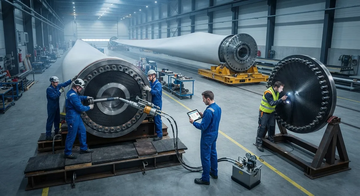
Every blade on a commercial wind turbine is held to the hub by a ring of steel bolts passing through the blade root laminate. That ring is not a simple fastening detail; it is the highest-loaded and most fatigue-critical joint in the entire turbine structure. Each flapwise bending cycle
Introduction
Every blade on a commercial wind turbine is held to the hub by a ring of steel bolts passing through the blade root laminate. That ring is not a simple fastening detail; it is the highest-loaded and most fatigue-critical joint in the entire turbine structure. Each flapwise bending cycle of a 100-meter blade applies cyclic axial loads to the root bolts in the millions, and a root connection failure typically means blade loss, hub damage, and months of downtime. It is no surprise that root connection design is one of the first areas blade engineers revisit when a turbine is upscaled or a new material system is introduced.
Two connection architectures dominate the industry: T-bolt connections, in which a threaded insert is drawn against a machined cavity inside the laminate, and threaded stud connections, in which the bolt threads into a steel bushing bonded into the root. Both must survive 20-25 years of loading, carry tens of tons of static thrust, and be installed reliably in a factory or field environment. This article compares the two designs on load path, fatigue behavior, and qualification, and explains why bolt fixture certification under IEC 61400-5 has become a purchase requirement for blade manufacturers and turbine OEMs.
The Two Dominant Root Connection Designs
A root connection transfers blade bending moments and axial forces into the pitch bearing flange through a bolt circle. In a T-bolt connection, a steel T-headed insert is placed in a machined cavity at the root end of the laminate. When the outer bolt is tightened, the insert is drawn outward until its T-head bears against the cavity floor, clamping the laminate between the T-head and the bolt head or washer. The load path runs from bolt tension through the T-head and into the laminate in compression.
A stud connection instead bonds a steel bushing with an internal thread into a drilled hole in the root laminate. A threaded stud is screwed into the bushing, and the outer nut clamps the bearing flange against the root face. Here the load path runs from the stud threads into the bushing and from the bushing's bonded surface into the laminate. Because the two designs load the laminate differently — one in localized bearing, the other through an adhesive bond — they differ in edge distance sensitivity, root thickness requirements, and repairability.
Load Path and Preload Mechanics
Regardless of architecture, the root joint works because the bolts are preloaded far beyond the service load they carry. Tightening stretches each bolt to 60-80% of its proof load, clamping the root and bearing flange together so that service loads change bolt tension by only a few percent rather than by the full load amplitude. If preload is lost — through embedding, creep, or temperature cycles — the bolt begins to carry full cyclic load and fatigue life collapses.
Load introduction differs between the designs. In a T-bolt, the tension force is introduced to the laminate at the cavity floor through the T-head bearing area; in a stud connection, it is introduced through the bonded bushing surface over a longer length. This difference shows up in fatigue testing: T-bolt connections concentrate strain near the cavity bottom and demand careful control of cavity geometry and edge distance, while stud connections distribute the load more evenly but depend entirely on the quality of the bushing bond to the laminate.
Design Parameters at a Glance
The table below summarizes typical design parameters for a modern multi-megawatt blade root:
| Parameter | Typical Range (MW-scale blade) |
|---|---|
| Bolt diameter | M30 to M36 |
| Bolt count per root | 60 to 100+ |
| Pitch circle diameter | 1,700 to 2,500 mm |
| Bolt preload | 60-80% of proof load |
| Root laminate thickness | 60 to 120 mm |
| Design fatigue life | 20-25 years, 10 million+ load cycles |
Bolt material is typically high-strength alloy steel (42CrMo4 class) heat-treated to property classes 10.9 or 12.9, with zinc or Dacromet-type coatings for corrosion resistance. The bolt circle must balance three conflicting demands: enough edge distance to prevent laminate splitting, enough bolt-to-bolt pitch to avoid local overload, and a pitch circle diameter that fits the pitch bearing flange.
T-Bolt versus Stud: Direct Comparison
| Criterion | T-Bolt Connection | Stud Connection |
|---|---|---|
| Load introduction | Bearing of T-head on cavity floor | Bonded bushing surface |
| Fatigue-critical detail | Cavity bottom geometry, edge distance | Bushing-to-laminate bond quality |
| Sensitivity to root thickness | Requires deeper root to house the cavity | More forgiving of thinner roots |
| Installation access | Blind-side installation from outside | Bushing bonded before bolt assembly |
| Repairability | Insert replaceable with careful machining | Damaged bond requires laminate rework |
| Typical application | Large onshore and offshore blades | Mid-size and high-volume blades |
Both designs are proven in the field; the choice is driven by blade size, manufacturing process, and the fatigue test data available for the specific bolt fixture configuration.
Bolt Fixture Qualification and IEC 61400-5
Bolt fixtures — the T-head inserts or stud bushings embedded in the root laminate — are structural components in their own right, and their qualification follows the blade design standard IEC 61400-5. The standard requires documented proof of static strength, fatigue strength, and failure mode control for the root connection, including component-level fatigue tests at realistic load ratios, pull-out and push-through tests, and validation of clamping force retention over time.
The industrialization of certified bolt fixtures is visible in the supply chain. Kineco Exel, the Indian composites manufacturer, produces IEC 61400-5 certified bolt fixtures at its Banda plant in Uttar Pradesh, supplying blade makers with qualified T-bolt and stud components rather than leaving connection design to in-house trial. This shift — from bespoke in-house details to certified, catalog-available bolt fixtures — is how the wind industry is absorbing the demand created by increasingly large blades.
Installation and Quality Assurance
- Torque and tension control: Bolts are tightened with hydraulic tensioners or torque wrenches to a defined preload, and many OEMs now require ultrasonic elongation measurement to verify preload rather than relying on torque alone.
- Surface preparation for bonding: For stud connections, the drilled hole and bushing surface must be cleaned, grit-blasted, and bonded with an approved adhesive under controlled temperature and humidity; bond voids are the dominant root failure initiator in stud designs.
- Cavity machining control: For T-bolt designs, cavity depth, diameter, and concentricity are machined to tight tolerances; off-tolerance cavities shift the bearing contact and reduce fatigue life.
- Inspection: Ultrasonic inspection of the bond line and cavity region, bolt preload records, and periodic in-service torque audits are standard elements of root connection quality programs.
Frequently Asked Questions
Which root connection is stronger: T-bolt or stud?
At comparable bolt diameters and root thicknesses, neither design is categorically stronger — both are sized to the same design loads and fatigue targets. The practical differences are in how load is introduced and where failure initiates. T-bolt connections carry very high ultimate loads through bearing, which suits the thick roots of large offshore blades, while stud connections spread the load over a longer bonded length and are common in higher-volume mid-size blades. What matters more than the architecture is the qualification evidence: an IEC 61400-5 certified fixture with documented fatigue data will outperform an uncertified equivalent regardless of type.
Why do root bolts fail in fatigue even though they are preloaded?
Preloaded bolts fail in fatigue when the preload is lost over time. Embedding of the laminate under the T-head or nut, creep of the bonded bushing, and temperature-driven expansion differences all relax the clamping force; once the service load exceeds the residual preload, the bolt experiences full load cycles and its fatigue life drops by orders of magnitude. This is why design practice holds preload at 60-80% of proof load, why coatings are specified against corrosion, and why field torque audits are scheduled. In stud connections, a bond failure does the same thing: the bushing stops sharing load and the stud begins to carry the full bending cycle.
What does IEC 61400-5 certification of a bolt fixture actually cover?
IEC 61400-5 is the international standard for wind turbine blade design, and it requires the root connection to be verified against static strength, fatigue strength, and failure mode criteria. For a bolt fixture, certification covers component-level fatigue testing under representative load ratios, static pull-out and push-through testing, clamping force retention validation, material and heat-treatment traceability, and documented installation procedures. A certified fixture gives the blade manufacturer pre-qualified connection data, which shortens blade certification and reduces the risk of root failures discovered late in prototype testing.
Conclusion
The blade root connection is a deceptively simple bolted joint carrying some of the highest fatigue loads in the wind industry. T-bolt and stud connections remain the two proven architectures, each with a clear load path, fatigue-critical detail, and application sweet spot. The competitive differentiator in 2026 is qualification: IEC 61400-5 certified bolt fixtures with documented fatigue data, produced at scale by suppliers such as Kineco Exel's Banda plant, are becoming the default choice for blade makers. For engineers selecting a root connection, the practical checklist is bolt circle sizing, preload management, fixture certification evidence, and an installation QA program that protects the bond and the cavity from day one.
For material selection and root laminate design support, explore our carbon fiber reinforcement range for wind energy, or contact our engineering team to discuss root connection materials, testing, and qualification for your blade program.
Part of topic
Related Articles
- Carbon Fiber Drone Blades and Propellers: Stiffness, Balance and Noise Reduction
- Fiberglass Filament Wound Tubes: Cost-Effective Alternative to Carbon Fiber
- Filament Wound Epoxy Tube Design: Wall Thickness, Fiber Angle and Load Optimization
- Filament Wound Epoxy Tubes: Testing Standards and Quality Assurance
- Filament Wound Epoxy Tubes Manufacturing: Process and Quality Control
- Filament Wound Fiberglass Tube: Process Parameters and Performance vs Carbon Fiber
Interested in Our Products?
Contact our team for competitive pricing and technical specifications.
Get a QuoteRelated Products

Carbon Fiber Plate — 3K Twill T700 3.0mm
Medium-thickness 3.0mm carbon fiber plate offering significantly higher load capacity while maintaining attractive 3K twill finish. Suitable for structural brackets, reinforcement plates, and load-bearing panels.

Custom Carbon Fiber Medical Device Components
Medical-grade carbon fiber components manufactured for imaging equipment, surgical instruments, and patient support systems. Carbon fiber's radiolucency (X-ray transparency) and high strength-to-weight ratio make it ideal for CT scanner beds, wheelchair frames, surgical robot arms, and MRI-compatible accessories. Biocompatible resin systems available.
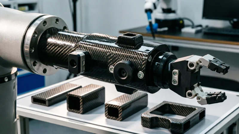
Carbon Fiber Robot End Effector Link — Custom Shape & Sensor Integration
Custom-shaped carbon fiber end effector links for robotic arms. Designed for automation integrators and research labs requiring lightweight, rigid connections between the robot wrist and gripper/tool. Can incorporate sensor mounting bosses, cable routing channels, and quick-change interfaces.
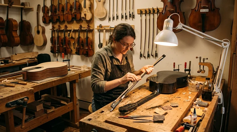
Custom Carbon Fiber Musical Instrument Parts
Carbon fiber components for musical instrument manufacturing offering superior dimensional stability, low weight, and consistent acoustic properties. We produce carbon fiber bows, guitar necks, violin chin rests, drum shells, and wind instrument bodies. Carbon fiber instruments are immune to humidity changes and temperature fluctuations that affect wooden instruments.
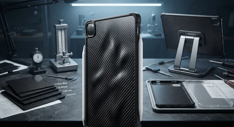
Carbon Fiber Tablet Case — Ultra-Light Protective Shell
Lightweight carbon fiber protective case for tablets and iPads. Molded from T700 3K prepreg with reinforced corner protection. Adds minimal weight while providing superior rigidity and drop protection compared to polycarbonate or silicone cases. Ideal for field workers, enterprise deployments, and professionals requiring durable tablet protection.