
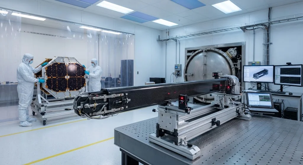
The satellite industry is undergoing a fundamental transformation as mega-constellations like Starlink, OneWeb, and Kuiper drive unprecedented production volumes for deployable structures. These structures — primarily carbon fiber reinforced polymer (CFRP) booms and solar array substrat
Introduction
The satellite industry is undergoing a fundamental transformation as mega-constellations like Starlink, OneWeb, and Kuiper drive unprecedented production volumes for deployable structures. These structures — primarily carbon fiber reinforced polymer (CFRP) booms and solar array substrates — must survive the violent vibrations of launch, deploy reliably in the vacuum of space, and maintain dimensional stability across temperature extremes ranging from −180°C to +150°C. For carbon fiber suppliers and composite manufacturers, the satellite deployable structure market represents a high-value, high-specification application where material performance directly determines mission success.
Current projections indicate that satellite constellation deployments will require 15,000-20,000 deployable boom structures and 8,000-12,000 solar array substrate panels annually through 2030. This production volume — a ten-fold increase from traditional geostationary satellite demand — is driving standardization of CFRP specifications, automation of manufacturing processes, and qualification of new material systems optimized for high-rate production. This article examines the technical requirements for satellite deployable structures, analyzes the CFRP material specifications, and provides guidance for manufacturers entering this demanding market segment.
Deployable Boom Design Requirements
CFRP booms serve as the primary structural elements for satellite antenna reflectors, solar array deployment mechanisms, and instrument pointing structures. These components must meet stringent requirements that push the limits of composite material performance:
- Dimensional stability: Booms must maintain straightness within ±0.1 mm over 2-5 meter lengths after deployment, with minimal springback or creep over the mission lifetime of 15-20 years. This requires CFRP laminates with near-zero coefficient of thermal expansion (CTE) achieved through precise fiber orientation control.
- Deployment reliability: Mechanical deployment mechanisms must achieve 99.99% reliability across thousands of deployment cycles during ground testing and single-shot deployment in orbit. CFRP boom hinges and latching mechanisms must function without lubrication in vacuum conditions.
- Mass efficiency: Every kilogram of structural mass saved in deployable structures translates to additional payload capacity or extended mission life. Target specific stiffness for satellite booms is 150-200 GPa/(g/cm³), exceeding the performance of aluminum alloys by 3-4 times.
- Thermal cycling resistance: Booms experience 50,000-100,000 thermal cycles over a 15-year mission as the satellite moves between sunlight and eclipse. CFRP laminates must maintain mechanical properties and dimensional stability without microcracking or delamination.
CFRP Material Specifications for Space
Satellite deployable structures require specialized CFRP material systems that differ significantly from aerospace or industrial grades:
| Property | Space-Grade CFRP | Aerospace-Grade CFRP | Significance for Deployables |
|---|---|---|---|
| Fiber modulus | High-modulus (M40J, M50J, M60J) | Intermediate-modulus (T800, T1100) | Higher modulus = lower CTE = better dimensional stability |
| Matrix resin | Space-qualified epoxy or cyanate ester | Standard aerospace epoxy | Low outgassing for vacuum compatibility |
| CTE (fiber direction) | −0.5 to −1.0 × 10⁻⁶/°C | −0.2 to −0.5 × 10⁻⁶/°C | Near-zero CTE critical for boom straightness |
| Outgassing (TML) | < 1.0% per ASTM E595 | < 2.0% per ASTM E595 | Prevents contamination of optical instruments |
| Fiber volume fraction | 58-62% | 55-60% | Higher FVF improves stiffness and CTE control |
| Interlaminar shear strength | ≥ 70 MPa | ≥ 60 MPa | Resists deployment-induced stresses |
| Operating temperature range | −180°C to +150°C | −55°C to +120°C | Wider range for orbital thermal environment |
Solar Array Substrate Design
Solar array substrates are the structural panels that support photovoltaic cells and distribute deployment loads. These components face unique challenges that differentiate them from other satellite structures:
- Flex-rigid architecture: Modern solar arrays use flexible blanket substrates that fold during launch and deploy to flat panels in orbit. CFRP face sheets with honeycomb or foam cores provide the required stiffness while maintaining flexibility for stowed configuration.
- Thermal expansion matching: The CFRP substrate must have CTE closely matched to silicon solar cells (CTE ≈ 2.6 × 10⁻⁶/°C) to prevent cell cracking during thermal cycling. This requires quasi-isotropic CFRP layups with carefully balanced fiber orientations.
- Electrical grounding: Solar array substrates must provide electrical grounding paths for electrostatic discharge protection. Carbon fiber's inherent conductivity is advantageous, but must be managed to prevent galvanic corrosion with aluminum cell interconnects.
- Micrometeoroid resistance: Substrates must withstand hypervelocity micrometeoroid impacts without catastrophic failure. Multi-layer CFRP construction with intermediate adhesive layers provides impact energy absorption.
Manufacturing Challenges for High-Rate Production
The transition from low-rate geostationary satellite production to high-rate constellation manufacturing requires fundamental changes in CFRP fabrication processes:
- Automated fiber placement: AFP systems are replacing hand layup for boom manufacturing, reducing cycle times from 40-60 hours per boom to 8-12 hours while improving dimensional consistency. However, AFP equipment investment of $2-5 million per system requires high production volumes to justify.
- Cure cycle optimization: Space-grade CFRP requires carefully controlled cure cycles with slow ramp rates (1-2°C/minute) and extended dwell times to minimize residual stresses. Optimized cure cycles reduce cycle time by 20-30% while maintaining dimensional stability specifications.
- Non-destructive inspection: 100% ultrasonic inspection is required for flight-critical deployable structures, with defect acceptance criteria more stringent than aerospace applications. Automated inspection systems processing 50-100 m²/hour are essential for high-rate production throughput.
- Dimensional verification: Boom straightness and solar array flatness must be verified using laser tracking systems with ±0.05 mm accuracy. In-process monitoring during AFP layup can reduce post-cure dimensional rejections by 40-60%.
Mega-Constellation Market Impact
The emergence of mega-constellations has fundamentally changed the economics and technical requirements for satellite deployable structures:
- Production volume scaling: Starlink alone is projected to require 5,000-7,000 deployable boom sets annually, compared to 200-300 for traditional geostationary programs. This volume enables automation investment and material standardization that reduces per-unit costs by 30-40%.
- Design-for-manufacturing: Constellation satellites prioritize producibility over performance optimization, driving CFRP designs toward simpler geometries, standardized ply schedules, and reduced inspection requirements for non-critical structures.
- Supply chain maturation: The predictability of constellation production schedules enables CFRP suppliers to invest in dedicated capacity and inventory programs, reducing lead times from 16-20 weeks to 8-12 weeks for qualified material systems.
- Qualification streamlining: Constellation operators are developing expedited qualification programs that accept higher initial risk in exchange for faster production ramp, creating opportunities for new CFRP suppliers to enter the market.
Frequently Asked Questions
What makes space-grade CFRP different from aerospace-grade material?
Space-grade CFRP differs from aerospace-grade material in three critical areas. First, fiber selection favors high-modulus variants (M40J, M50J, M60J) over intermediate-modulus fibers (T800, T1100) to achieve near-zero coefficient of thermal expansion for dimensional stability. Second, matrix resins must meet strict outgassing requirements (TML < 1.0% per ASTM E595) to prevent contamination of optical instruments and solar cells in vacuum. Third, quality acceptance criteria are more stringent, with 100% ultrasonic inspection and tighter dimensional tolerances (±0.1 mm over 5-meter lengths) than typical aerospace applications. These requirements increase material cost by 40-60% compared to aerospace grades but are essential for mission-critical deployable structures.
How do CFRP booms achieve near-zero thermal expansion?
Near-zero thermal expansion in CFRP booms is achieved through precise control of fiber orientation in the laminate layup. Carbon fibers have negative CTE in the fiber direction (−0.5 to −1.0 × 10⁻⁶/°C) and positive CTE in the transverse direction (+20 to +30 × 10⁻⁶/°C). By balancing the number of plies at 0°, ±45°, and 90° orientations, designers can create quasi-isotropic laminates with overall CTE near zero. High-modulus fibers (M40J, M50J) are preferred because their higher axial modulus amplifies the negative CTE effect, allowing fewer 0° plies to achieve the target expansion coefficient. The manufacturing challenge is maintaining fiber orientation accuracy during automated placement, as even 1-2° deviation can shift CTE by 0.3-0.5 × 10⁻⁶/°C.
What are the primary failure modes for deployable CFRP structures in orbit?
The primary failure modes for deployable CFRP structures in orbit include: (1) deployment mechanism jamming due to cold-welding of unlubricated metal surfaces in vacuum, (2) boom straightness degradation from microcracking during thermal cycling, (3) delamination at hinge regions from repeated deployment stresses, and (4) dimensional drift from moisture absorption and desorption cycles during ground storage and on-orbit operations. Mitigation strategies include: solid lubricant coatings (MoS₂) for deployment mechanisms, toughened resin systems for improved crack resistance, additional plies at hinge regions, and controlled humidity storage prior to launch. Ground testing must simulate 100,000 thermal cycles to validate long-term performance, requiring accelerated testing facilities that can reproduce the space thermal environment.
Conclusion
Satellite deployable structures represent the pinnacle of carbon fiber composite engineering, requiring material performance that pushes the boundaries of dimensional stability, thermal resistance, and deployment reliability. The emergence of mega-constellations is transforming this market from a low-volume, high-specification niche to a high-rate production environment where manufacturing efficiency and material standardization are as important as ultimate performance. For CFRP suppliers, success in this market requires investment in space-qualified material systems, automated manufacturing capabilities, and quality infrastructure that meets the stringent requirements of constellation operators. As satellite deployments accelerate toward 15,000-20,000 units annually, the CFRP manufacturers who can deliver consistent quality at production scale will capture significant value in this demanding but rewarding market segment.
For satellite manufacturers and constellation operators evaluating CFRP supply strategies, understanding the material specifications and manufacturing requirements for deployable structures is essential. Explore our space-grade carbon fiber products, including high-modulus fibers and space-qualified resin systems optimized for deployable structures, or contact our aerospace team to discuss material qualification requirements for your satellite program.
Part of topic
Related Articles
- Carbon Fiber Mooring for Floating Offshore Wind: Fatigue and Corrosion in Deep Water
- Carbon Fiber Bicycle Frame Optimization: Layup Design and Manufacturing for Competitive Racing
- Carbon Fiber CFRP Retrofit for Infrastructure: Bridge and Building Seismic Strengthening
- Carbon Fiber Medical Imaging Equipment: Lightweight Gantry and Couch Structures for MRI/CT
- Carbon Fiber EV Battery Enclosures: Crash Safety and Electromagnetic Shielding Design
- Carbon Fiber Structures for Low-Altitude Economy: UAV Airframes and eVTOL Components