
Transmission towers are among the most asset-heavy infrastructure in the power grid, and their crossarms — the horizontal arms that carry the conductor attachment points — are deceptively simple components with demanding engineering requirements. A crossarm must resist bending and buckl
Introduction
Transmission towers are among the most asset-heavy infrastructure in the power grid, and their crossarms — the horizontal arms that carry the conductor attachment points — are deceptively simple components with demanding engineering requirements. A crossarm must resist bending and buckling under conductor and ice loads, survive decades of weather exposure, and maintain electrical clearance between phases and to the tower structure. For more than a century, steel angle sections have done this job, but they bring two persistent problems: corrosion in coastal and industrial corridors, and the need for insulator strings long enough to keep the energized conductor clear of the grounded steel.
Carbon fiber reinforced polymer (CFRP) crossarms solve both problems at once. Because carbon fiber is an electrical insulator by nature, a CFRP crossarm can shorten or eliminate suspension insulator strings, reducing tower height and footprint. Because it does not corrode, it removes the maintenance burden in salt-laden and polluted environments. And because its stiffness-to-weight ratio is far higher than steel, it offers a lightweight structure with excellent buckling resistance. This article explains how CFRP crossarms are designed, how insulators integrate with the composite arm, and where the technology is being adopted in high-voltage line design.
Why Utilities Are Moving to Composite Crossarms
The driver is a combination of line performance, maintenance cost, and environmental footprint. Steel lattice towers with porcelain or glass insulator strings dominate existing lines, but the economics of new lines and the retrofit market are shifting toward composites:
- Corrosion elimination: Steel crossarms in coastal regions typically need recoating or replacement within 15-25 years; CFRP arms are specified for 40+ year service with no coating maintenance.
- Reduced tower height: With insulator integration, the crossarm itself provides the insulation, lowering the conductor attachment point and cutting tower height by 3-10 meters.
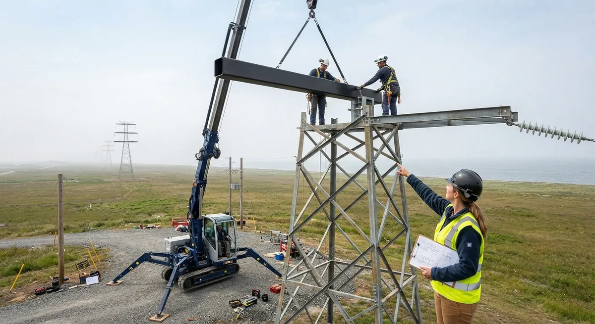
- Lower transport and erection cost: A composite crossarm weighs 70-80% less than the steel assembly it replaces, enabling manual or light-crane erection in remote terrain.
- Compact line corridors: Insulator-integrated composite arms can reduce the right-of-way width required for a line, which matters in urban and land-constrained regions.
China has been the early adopter, with provincial grid operators piloting CFRP crossarms on 110 kV to 330 kV lines since the early 2010s, and the technology is now spreading to India, the Middle East, and Southeast Asia where coastal and desert environments punish steel hardware.
How a CFRP Crossarm Carries Conductor Loads
A crossarm is a cantilever structure: the conductor tension and vertical weight are transferred through the insulator attachment point into the arm, which must then resist bending and buckling without excessive deflection. The CFRP crossarm is typically a pultruded or resin-transfer-molded hollow box section, with fiber architecture tuned to the loading:
- Axial fibers along the arm length carry the bending moments, giving a tensile modulus of 120-150 GPa and a strength of 1,500-2,400 MPa.
- Diagonal and hoop layers resist web buckling of the box section walls and control torsional response under asymmetric ice or wind loads.
- The hollow section maximizes second moment of area for the weight, so a composite arm can be lighter than steel while achieving the same or better buckling resistance.
Buckling is the governing failure mode for long slender crossarms, and it is where composite design excels. The buckling load of a column scales with stiffness; with roughly 2-3x the stiffness-to-weight ratio of steel, a CFRP crossarm of comparable geometry resists buckling with substantially less material. Design verification typically combines finite element analysis with full-scale cantilever tests to the applicable tower loading standards.
Insulator Integration: Design Approaches
The most distinctive feature of CFRP crossarms is their ability to integrate the insulation function. There are two main design approaches, and the choice affects the whole tower architecture:
| Design approach | Conventional steel crossarm + insulator string | Insulated CFRP crossarm |
|---|---|---|
| Insulator strings | 2-4 suspension strings per phase | Eliminated or shortened to arcing horns |
| Typical 110 kV tower height | 28-35 m | 25-30 m (3-5 m lower) |
| Right-of-way width | Full standard corridor | Up to 20-30% narrower |
| Corrosion exposure | Steel hardware recoat every 10-20 years | None — no steel in the arm |
| Weight per 110 kV arm assembly | 300-600 kg | 80-150 kg |
| Service life expectation | 25-40 years | 40+ years |
| Main inspection regime | Insulator washing, hardware checks | Visual + IR inspection only |
In the fully insulated approach, the CFRP arm itself is the insulator — the energized conductor attaches to an end fitting on the arm, and the composite provides the creepage distance. This requires careful design of the end fittings to control the electric field, since carbon fiber has low volume resistivity and any exposed fiber end becomes a field concentration point. End fittings are typically engineered with stress-relief grading, and the arm surface may include a polymer coating or hydrophobic skirt to extend creepage distance and shed pollution. In the partially insulated approach, a shortened insulator string remains, but the composite arm replaces the long structural span, reducing both height and weight.
Corrosion-Free Performance in Coastal and Industrial Corridors
Corrosion is the single largest maintenance driver on transmission lines. Salt-laden coastal air, industrial sulfur compounds, and acid rain attack steel crossarms, galvanized hardware, and the fittings that hold insulators. The failure modes are familiar to every utility engineer: rusted crossarm angle sections with reduced section area, seized bolts that make replacement dangerous, and accelerated corrosion at dissimilar-metal contact points. CFRP eliminates the mechanism entirely:
- No oxidation: carbon fiber and the polymer matrix are electrochemically inert; there is no steel to corrode and no coating to refresh.
- No galvanic coupling: all-composite or isolated-composite attachment hardware removes the bimetallic corrosion cell between steel arm and galvanized tower.
- Stable performance in pollution: the composite surface sheds pollutants more readily and supports hydrophobic coating, maintaining creepage performance where porcelain would accumulate conductive contamination.
For coastal projects, the maintenance saving is the headline financial case: eliminating one recoat-and-inspection cycle over a 25-year horizon can pay for a significant share of the CFRP arm premium. In industrial corridors, the same benefit applies without the need for live-line washing programs.
Qualification and Standards
CFRP crossarms are a relatively young product category, and qualification follows a combination of composite and line-design standards. Typical acceptance testing includes:
- Mechanical verification: full-scale cantilever and buckling tests at 2-2.5x normal conductor load, plus long-term creep testing under sustained load.
- Electrical verification: lightning impulse and power-frequency withstand tests on the insulated arm and end fittings, verifying the creepage distance and field grading.
- Environmental testing: UV aging, salt-spray, and thermal cycling representative of the service environment, validating the 40+ year design life.
- Composite process control: fiber volume fraction, void content, and cure verification per the applicable composite standard to ensure batch consistency.
Utilities typically require design review against their tower loading codes (such as the relevant IEC 60826-derived national codes) and a demonstration line segment before fleet-wide deployment, which is why early-adopter utilities have built proving-ground line sections to accumulate service experience.
Frequently Asked Questions
Is carbon fiber safe to use as an insulator in high-voltage lines?
Yes, with proper design. Carbon fiber itself has low volume resistivity, so a CFRP crossarm cannot be treated as a simple insulator the way porcelain is. The key is engineering the end fittings and surface so the electric field is controlled: stress-relief grading at the live end, adequate creepage distance, and a hydrophobic coating or skirt where needed. With these measures, insulated CFRP crossarms have passed lightning impulse and power-frequency withstand tests on operating 110 kV to 330 kV lines. The design discipline is the same as for any composite insulation system — field grading and creepage management — and it is well established in the industry.
How much weight does a CFRP crossarm save compared to steel?
A typical 110 kV steel crossarm assembly weighs roughly 300-600 kg including the structural sections and attachment hardware. An equivalent CFRP crossarm weighs 80-150 kg — a 70-80% reduction. This is why composite arms can be erected with manual labor or small cranes in remote terrain, and why they reduce transport cost in difficult access. On the tower, the weight reduction also lowers the overturning moment on the tower body, which can reduce foundation size on new builds.
What is the service life of a CFRP transmission crossarm?
Manufacturers specify 40+ years for CFRP crossarms based on accelerated UV, salt-spray, and thermal cycling tests, against a typical steel recoat cycle of 10-20 years in coastal environments. The polymer matrix must be UV-stabilized and the fiber-matrix interface protected at cut edges and drilled holes. Field demonstration segments in China have now accumulated more than a decade of service on 110 kV lines without material degradation. Like all composite infrastructure, the achievable life depends on process quality and correct installation, which is why qualified manufacturers provide process verification data with each arm.
Conclusion
CFRP transmission tower crossarms combine structural and electrical functions that steel has never been able to unify: they carry conductor loads with superior buckling resistance, provide the insulation that previously required long insulator strings, and eliminate the corrosion burden that drives transmission maintenance budgets. The result is a shorter tower, a narrower corridor, and a 40-year maintenance-light asset in the environments where steel fails earliest. For utilities planning new lines or retrofitting corroded corridors, the composite crossarm is no longer a laboratory concept — it is a proven option with a decade of in-service data.
To evaluate CFRP crossarm material and profile options for your line design, explore our carbon fiber structural profiles or contact our engineering team for composite crossarm design and qualification support.
Part of topic
Related Articles
- Carbon Fiber Tube for Sale: Comparing Listings and Avoiding Bad Specs
- Carbon Fiber Engine Parts: High-Temperature Performance for Racing and Performance Vehicles
- Carbon Fiber Body Parts: Automotive Exterior Panels and Structural Components
- Carbon Fiber Drone Body Manufacturing: Monocoque Design and Production Methods
- Carbon Fiber Drone Parts Supplier: FPV Frames, Arms and Structural Components
- Filament Wound Epoxy Tubes: Industrial Applications from Oil and Gas to Aerospace