
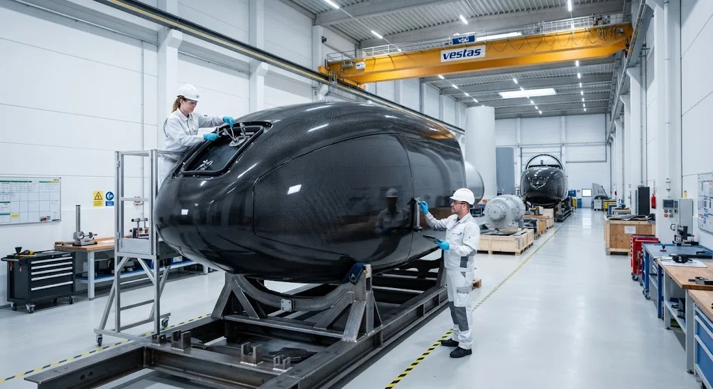
Carbon fiber nacelle covers represent a critical lightweighting opportunity for next-generation wind turbines, reducing nacelle mass by 20-35% while improving aerodynamic performance and service accessibility. This article examines carbon fiber nacelle cover design, manufacturing methods, and the structural-aerodynamic trade-offs that optimize turbine performance.
Introduction
The nacelle — the housing that encloses the gearbox, generator, control systems, and auxiliary equipment atop the wind turbine tower — represents 15-20% of total turbine mass for modern direct-drive and geared designs. Nacelle covers, typically accounting for 3-5% of nacelle mass (2-8 tonnes for a 5 MW turbine), present a high-value lightweighting opportunity because they are non-structural aerodynamic fairings where mass reduction directly reduces tower loading, crane requirements for maintenance, and yaw system energy consumption.
Transitioning nacelle covers from glass fiber reinforced polymer (GFRP) or sheet molding compound (SMC) to carbon fiber reinforced polymer (CFRP) composites enables 20-35% mass reduction while maintaining or improving impact resistance, UV durability, and fire performance. However, the material cost premium of carbon fiber (typically 3-5x glass fiber) requires careful engineering optimization to justify the weight savings through system-level performance gains. This article examines the design methodologies, manufacturing considerations, and performance trade-offs that define carbon fiber nacelle cover applications in modern wind turbines.
Nacelle Cover Design Requirements
Nacelle covers must satisfy multiple functional requirements that influence material selection and structural design:
- Aerodynamic shaping: Nacelle covers define the external aerodynamic profile of the turbine, influencing drag coefficient (Cd), flow separation characteristics, and noise generation. Carbon fiber enables thinner wall sections (2-4 mm vs. 5-8 mm for GFRP) that maintain aerodynamic surface quality while reducing weight, particularly important for the curved aft section where flow attachment is critical for minimizing hub losses.
- Impact resistance: Nacelle covers must withstand bird strikes, hail, and ice throw impacts without penetration or cracking. Carbon fiber composites provide superior impact resistance through energy absorption mechanisms — fiber breakage, delamination, and matrix cracking distribute impact energy over larger areas than GFRP equivalents. Standard test: 1 kg ice ball at 90 m/s (IEC 61400-1 hail simulation) without penetration.
- Access and serviceability: Nacelle covers incorporate access doors, inspection hatches, and removable panels for maintenance access. Carbon fiber enables lighter, thinner panels that can be opened by single technicians without crane assistance, reducing maintenance time by 30-50% compared to heavier GFRP panels requiring mechanical lifting.
- Fire performance: Nacelle covers must meet fire resistance requirements per IEC 61400-1 and national building codes. Carbon fiber composites with fire-retardant resin systems achieve Class B1 fire ratings (flame spread index <25) while maintaining structural integrity at temperatures up to 300°C for 30 minutes.
- UV and weathering durability: Nacelle covers are exposed to continuous UV radiation, temperature cycling, and precipitation. Carbon fiber composites with UV-resistant gel coats or topcoats maintain surface quality and mechanical properties for 20-25 year design lives, matching or exceeding GFRP durability.
Lightweighting Strategies
Carbon fiber nacelle cover lightweighting employs several engineering approaches to maximize mass reduction while controlling cost:
- Sandwich construction: Carbon fiber face sheets (0.5-1.0 mm each) bonded to foam or honeycomb cores (10-25 mm thickness) create nacelle cover panels with 40-60% mass reduction compared to solid GFRP laminates of equivalent stiffness. Core materials include closed-cell PVC foam (density 80-150 kg/m³) and Nomex honeycomb (density 48-144 kg/m³), selected based on impact resistance requirements and manufacturing complexity.
- Hybrid carbon-glass designs: Selective replacement of glass fiber with carbon fiber in high-stress regions (curved sections, hinge points, door frames) while retaining GFRP in flat, low-stress areas achieves 15-25% mass reduction at 40-60% lower material cost than full-carbon designs. This approach requires careful interface design to manage the thermal expansion mismatch between carbon and glass fiber regions.
- Fiber orientation optimization: Tailored fiber orientations in curved nacelle cover sections align high-modulus carbon fibers with primary load paths, achieving 20-30% higher stiffness per unit weight compared to quasi-isotropic layups. Computer-controlled fiber placement enables variable angle tow steering that follows principal stress trajectories, reducing material waste by 15-20% compared to constant-angle designs.
- Topology optimization: Computational topology optimization identifies minimum-material nacelle cover geometries that satisfy aerodynamic, impact, and stiffness requirements. Topology-optimized carbon fiber nacelle covers achieve 25-35% mass reduction compared to conventionally designed GFRP covers while maintaining equivalent structural performance.
Manufacturing Methods
Carbon fiber nacelle covers require manufacturing processes that balance performance, production rate, and cost:
| Process | Fiber Volume Fraction | Void Content | Cycle Time | Unit Cost Premium vs. GFRP |
|---|---|---|---|---|
| Vacuum infusion | 45-55% | 2-4% | 8-16 hours | 2.5-3.5x |
| Prepreg autoclave | 55-60% | <1% | 4-8 hours | 3.5-5.0x |
| RTM (Resin Transfer Molding) | 50-58% | 1-3% | 2-4 hours | 2.0-3.0x |
| Compression molding (SMC equivalent) | 40-50% | 1-2% | 5-15 minutes | 1.8-2.5x |
Production rate requirements (200-500 nacelle covers per year for a 2 GW annual turbine market) favor RTM and compression molding processes, while prototype and low-volume applications may use vacuum infusion or prepreg autoclave for maximum performance.
System-Level Benefits
The mass reduction achieved through carbon fiber nacelle covers delivers measurable system-level performance improvements across multiple turbine subsystems:
- Tower loading reduction: Each kilogram saved at nacelle level reduces tower base bending moment by 0.5-1.0 kN·m (assuming 80-100 m hub height), potentially enabling tower wall thickness reductions of 1-3 mm. System mass savings: 5-15% tower mass reduction, translating to $20,000-80,000 per turbine in material savings.
- Yaw system optimization: Lighter nacelles reduce yaw moment of inertia by 15-25%, enabling smaller yaw motors (30-40% power reduction) or faster yaw response (20-30% improvement). Annual energy production gain: 0.3-0.5% from improved yaw tracking accuracy.
- Maintenance cost reduction: Lighter nacelle cover panels (30-50% weight reduction) enable manual handling without crane assistance for routine inspections and component replacement. Maintenance time reduction: 4-8 hours per service event, translating to $5,000-15,000 per turbine annually in avoided crane costs.
- Transportation logistics: Reduced nacelle mass simplifies transportation and installation logistics, potentially eliminating the need for specialized heavy-lift cranes for nacelle placement. Transportation cost reduction: 10-20% for overland transport to remote wind farm sites.
Cost-Benefit Analysis
The economic justification for carbon fiber nacelle covers depends on turbine size, production volume, and site-specific factors:
- Material cost premium: Carbon fiber nacelle covers cost $15,000-40,000 per turbine compared to $8,000-20,000 for GFRP equivalents, representing a $7,000-20,000 premium per turbine.
- System-level savings: Tower material savings ($20,000-80,000), yaw system savings ($5,000-15,000), and maintenance savings ($5,000-15,000 annually) total $30,000-110,000 per turbine over 20-year design life.
- Net present value: Discounted at 8% over 20 years, the net present value of carbon fiber nacelle cover investment ranges from $15,000-70,000 per turbine, with payback periods of 3-7 years depending on site conditions and turbine size.
- Break-even analysis: Carbon fiber nacelle covers become cost-effective for turbines >4 MW (where mass-related savings scale faster than material costs) and production volumes >100 units/year (where manufacturing learning curves reduce processing cost premiums).
Conclusion
Carbon fiber nacelle covers represent a technically mature and economically justified lightweighting opportunity for modern wind turbines, delivering system-level performance improvements that exceed the material cost premium through tower loading reduction, yaw system optimization, and maintenance cost savings. As wind turbine sizes continue to grow toward 15-20 MW classes, the mass-related benefits of carbon fiber nacelle covers will become increasingly significant, driving adoption from current niche applications to mainstream turbine specifications.
YongXian CarbonFiber
YongXian manufactures carbon fiber tubes, sheets, and custom composite parts from our Dezhou, China factory. With over 15 years of composite manufacturing experience, we supply carbon fiber components to aerospace, automotive, energy, and industrial customers worldwide.
Contact us for custom carbon fiber solutions.
Part of topic
Related Articles
- Carbon Fiber Mooring for Floating Offshore Wind: Fatigue and Corrosion in Deep Water
- Carbon Fiber Bicycle Frame Optimization: Layup Design and Manufacturing for Competitive Racing
- Carbon Fiber CFRP Retrofit for Infrastructure: Bridge and Building Seismic Strengthening
- Carbon Fiber Medical Imaging Equipment: Lightweight Gantry and Couch Structures for MRI/CT
- Carbon Fiber EV Battery Enclosures: Crash Safety and Electromagnetic Shielding Design
- Carbon Fiber Structures for Low-Altitude Economy: UAV Airframes and eVTOL Components