
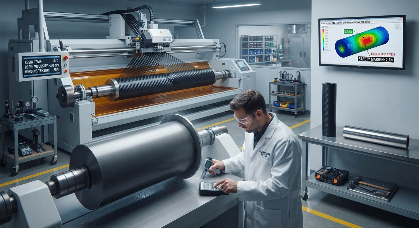
Technical B2B analysis of carbon fiber industrial roll coverings for high-speed winding, printing, and web handling machinery. Covers laminate architecture (HM, IM fiber systems), manufacturing processes (filament winding, roll wrapping, shrink-fit sleeves), application case studies in rotogravure printing, and total cost of ownership analysis for steel-to-CF roll retrofitting.
Carbon Fiber Roll Coverings: Transforming High-Speed Industrial Machinery
In modern high-speed web handling machinery — film casting lines, paper winding stations, textile finishing calenders, printing presses, and metal foil processing equipment — the performance of the process roll is the single most important factor determining line speed, product quality, and operational efficiency. A typical 3-meter-wide gravure printing press operating at 600 m/min runs 8–14 process rolls per color station, each of which must maintain dimensional stability within ±5 μm across the full face width during continuous operation. Carbon fiber composite roll coverings — thin-walled cylindrical shells made from high-modulus carbon fiber/epoxy laminate that are bonded or mechanically attached to a steel or aluminum core — have emerged as the enabling technology for next-generation machinery operating at line speeds exceeding 1,000 m/min with web widths up to 12 meters.
The business case for carbon fiber roll coverings is compelling across multiple industrial sectors. Compared to conventional hard-chrome-plated steel rolls, carbon fiber-covered rolls offer: (1) 70–85% reduction in rotational inertia, enabling faster acceleration/deceleration and reducing motor size requirements by 30–50%; (2) 5–10× higher specific stiffness (stiffness-to-weight ratio), eliminating the roll deflection that causes web wrinkling, misregistration, and uneven coating thickness; (3) near-zero coefficient of thermal expansion in the axial direction (-0.3 to +0.5 × 10⁻⁶/°C compared to 11.7 × 10⁻⁶/°C for steel), eliminating thermal growth-induced alignment changes during warm-up and process temperature shifts; (4) inherent corrosion resistance in chemically aggressive environments (acidic paper machine wet-ends, solvent-based printing ink systems, electrolytic plating baths); and (5) vibration damping coefficients 3–8× higher than steel, attenuating resonant vibration modes that cause barring and chatter marks on the processed web.
Material Systems and Laminate Architecture
The design of a carbon fiber roll covering requires careful optimization of laminate architecture to meet the combined requirements of flexural stiffness, hoop strength, thermal stability, and surface hardness. The most widely adopted material system for industrial roll coverings is a hybrid carbon fiber/epoxy laminate combining high-modulus (HM) and intermediate-modulus (IM) fiber grades in a tailored layup sequence:
- Primary structural plies (outer 60–75% of thickness): High-modulus carbon fiber (Toray M40J: 4,400 MPa tensile strength, 377 GPa modulus, or Mitsubishi K13D2: 3,800 MPa tensile strength, 483 GPa modulus) oriented in the axial (0°) direction provides bending stiffness and thermal stability. A typical 12-meter-long paper machine roll covering uses 60–80 axial plies of 190 g/m² HM prepreg, achieving an effective axial modulus of 280–350 GPa.
- Hoop reinforcement plies (inner 15–25% of thickness): Intermediate-modulus fiber (Toray T700S or T800S) oriented at ±45° and 90° (hoop) resists the centrifugal and nip pressures encountered during operation. At 1,200 m/min surface speed on a 400 mm diameter roll, the centrifugal stress in the covering exceeds 15 MPa; at a 120 kN/m nip load (typical for paper calenders), the hoop stress reaches 35–50 MPa. The ±45° plies also provide the primary load path for torque transmission from the roll core to the covering surface.
- Surface layer (outermost 1.0–2.0 mm): A ceramic particle-filled epoxy resin layer or a thin metallic sleeve (nickel or hard chrome, 0.3–0.8 mm) provides the requisite surface hardness (Rockwell C 55–65) and wear resistance for the specific web material being processed. For printing applications, a 0.5 mm electroless nickel coating with embedded silicon carbide particles (5–15 μm diameter, 20–40% volume fraction) achieves a surface hardness of 800–1,200 HV and a coefficient of friction adjustable between 0.25 and 0.60 by controlling the exposed particle density.
| Parameter | Hard-Chrome Steel Roll | CF Roll Covering (HM) — Winding | CF Roll Covering (IM) — Printing | Ceramic-Coated Aluminum Roll |
|---|---|---|---|---|
| Covering thickness (mm) | N/A (solid steel) | 4–12 | 3–8 | 0.3–1.5 (coating) |
| Axial bending stiffness (N·m²) | 4.5 × 10⁶ | 8.2 × 10⁶ | 5.8 × 10⁶ | 2.8 × 10⁶ |
| Rotational inertia (kg·m², 400mmØ × 3m) | 320 | 72 | 58 | 155 |
| Max surface speed (m/min) | 800 | 1,500 | 1,800 | 900 |
| Axial CTE (10⁻⁶/°C) | 11.7 | −0.3 to +0.5 | −0.5 to +1.0 | 23.0 |
| Surface hardness (Rockwell/Shore) | HRC 60–65 | HRC 55–65 (with sleeve) | Shore D 75–85 | HRC 70–80 |
| Vibration damping factor (ζ) | 0.002–0.005 | 0.015–0.025 | 0.020–0.030 | 0.003–0.008 |
| Nip load capacity (kN/m) | 150–250 | 80–150 | 60–120 | 50–100 |
| Operating temperature range (°C) | −30 to +200 | −40 to +160 | −40 to +180 | −30 to +350 |
| Roll weight (kg, 400mmØ × 3m) | 2,950 | 820 | 670 | 1,450 |
| Relative cost per roll (10 units/yr) | 1.0x (baseline: $18,000) | 3.5–5.0x | 2.5–4.0x | 1.8–2.5x |
| Service life (years, typical operation) | 3–5 | 8–15 | 6–12 | 2–4 |
Manufacturing Processes for CF Roll Coverings
Carbon fiber roll coverings are manufactured using one of three principal processes, selected based on the roll geometry, performance requirements, and production volume. Each process yields distinct laminate characteristics and cost profiles that must be matched to the specific industrial application.
Filament winding is the dominant manufacturing process for roll coverings above 500 mm face width, accounting for approximately 70% of production globally. A steel or aluminum core mandrel is mounted on a computer-controlled filament winding machine, and carbon fiber tow (12K–48K) impregnated with epoxy resin is wound onto the rotating mandrel at controlled tension (5–50 N per tow) and precise winding angles (±0.5° position accuracy). The winding pattern is programmed to achieve the specified laminate architecture: axial (0°) plies for bending stiffness are applied through longitudinal winding or by incorporating unidirectional prepreg tapes; hoop (±45° to 90°) plies for pressure retention are applied through circumferential winding. After the complete laminate is deposited to the design thickness (typically 4–15 mm), the assembly is cured in a controlled-temperature oven (120–160°C for 4–8 hours, ramp rate 0.5–2.0°C/min) while the mandrel continues to rotate at 2–10 RPM to prevent resin sag and ensure uniform thickness distribution. The cured covering is then machined to final dimensions on a precision roll grinder, achieving surface finish of Ra 0.2–0.8 μm and diametral tolerance of ±10–25 μm. Filament-wound coverings achieve fiber volume fractions of 55–65% and void contents below 1.0%.
Roll wrapping (prepreg layup) is preferred for smaller-diameter rolls (below 300 mm diameter) requiring the highest axial stiffness, such as spreader rolls and bending rolls in film stretching lines. Multiple plies of unidirectional carbon fiber prepreg are cut to precise width and wrapped around the mandrel with a controlled overlap (typically 30–50% of ply width per revolution), creating a continuous helical wrap. The prepreg layup allows the use of the highest-modulus fibers (M55J, K13D2, YS-95A) that are difficult to filament-wind due to their low strain-to-failure (0.3–0.5%). Cure and finishing processes are similar to filament winding, with the addition of a vacuum bag consolidation step to achieve void contents below 0.5%.
Shrink-fit sleeve technology — a more recent innovation developed jointly by European and Japanese composite manufacturers — produces a thin-walled (0.5–3.0 mm) carbon fiber sleeve that is manufactured separately, then shrink-fitted onto an existing steel or aluminum roll core. The sleeve is filament-wound or roll-wrapped to a slightly smaller inner diameter than the core's outer diameter (interference fit of 0.05–0.15% of diameter), cured, then heated to 120–180°C to expand the sleeve, which is then positioned over the cooled core. Upon cooling, the sleeve contracts onto the core with a radial clamping pressure of 5–15 MPa, creating a reliable mechanical interlock without adhesive bonding. This technology enables retrofitting of existing machinery — a significant advantage for paper mills and printing facilities with large installed bases of conventional steel rolls. A 2024 field study by the Technical Association of the Pulp and Paper Industry (TAPPI) documented a 350 m/min increase in line speed after retrofitting the press section rolls of a newsprint machine with carbon fiber shrink-fit sleeves, with a payback period of 11 months.
Application Case Studies: Printing Press Rolls
In high-speed rotogravure and flexographic printing, the dimensional stability and vibrational characteristics of the plate cylinder and impression roll directly determine print registration accuracy and defect rates. A 2025 benchmarking study of a 10-color rotogravure press operating at 700 m/min on 24 gsm polypropylene film — a common packaging substrate — compared conventional steel impression rolls against carbon fiber-covered rolls. The study reported: (1) color-to-color registration improved from ±0.15 mm (steel) to ±0.04 mm (carbon fiber) over a 2,000-meter run, a 73% reduction in registration variation; (2) web breaks reduced by 62%, from 1.8 per 10,000 linear meters to 0.7 per 10,000 linear meters; (3) gravure cylinder cell volume variation (a measure of ink transfer consistency) decreased from ±3.5% to ±1.2%; (4) the press was able to ramp from startup speed (100 m/min) to full production speed (700 m/min) in 45 seconds with CF rolls versus 95 seconds with steel rolls, due to the 78% reduction in roll inertia; and (5) waste during startup and changeover was reduced by 41%, from 185 linear meters to 109 linear meters per job change.
The thermal stability advantage of carbon fiber roll coverings was particularly evident in the printing study. During a typical 8-hour production shift, steel impression rolls experience 0.12–0.25 mm of axial thermal growth (from the 11.7 × 10⁻⁶/°C expansion coefficient and a 15–25°C temperature rise), requiring the press operator to make manual register adjustments every 45–90 minutes. Carbon fiber-covered rolls with near-zero axial CTE eliminated thermal growth-related registration drift entirely, maintaining register within ±0.02 mm over the full 8-hour shift without operator intervention.
Frequently Asked Questions
What is the expected payback period when switching from steel rolls to carbon fiber-covered rolls?
The payback period for carbon fiber roll covering investment depends on three primary factors: production line speed utilization, waste reduction, and maintenance cost savings. Based on detailed total cost of ownership (TCO) models developed by leading roll covering manufacturers for the 2025–2026 machinery market, the typical payback scenario by industry is as follows. For printing presses (gravure/flexo) running at ≥500 m/min: payback period of 8–16 months, driven by waste reduction (28–41% less startup waste), reduced register correction downtime (2.5–4.0 hours saved per 8-hour shift), and 40–60% reduction in impression roll regrinding frequency (steel rolls require regrinding every 12–18 months at $3,000–$8,000 per regrind; CF covering regrinding interval extends to 4–7 years). For paper machine press sections (newsprint, packaging grades): payback period of 11–20 months, driven by line speed increase (200–400 m/min additional speed), reduced web breaks (40–65% fewer breaks per day), and energy savings from reduced drive motor load (15–30% reduction in section drive power consumption). For film and foil winding lines (PET, BOPP, aluminum foil): payback period of 14–24 months, driven by improved wound roll quality (20–35% reduction in telescoping, wrinkles, and starring defects) and reduced mechanical maintenance from roll covering debonding and surface wear. At YongXian CarbonFiber, our standard TCO analysis includes these factors plus the extended service life (8–15 years for CF versus 3–5 years for steel) and the residual value of the composite covering (estimated at 25–40% of initial cost after 10 years, compared to near-zero scrap value for worn steel rolls).
Can existing steel rolls in a production line be retrofitted with carbon fiber coverings, or is a new roll required?
Both options are available, with the appropriate choice depending on the roll geometry, core condition, and performance requirements. The retrofitting option — using shrink-fit carbon fiber sleeves — is available for rolls with the following core conditions: minimum core diameter of 150 mm, maximum core diameter of 800 mm, core straightness within 0.05 mm/m, and core surface free of deep corrosion pits, cracks, or previous weld repairs. The retrofitting process involves: (1) precision grinding of the existing steel core to achieve uniform diameter within ±15 μm and surface finish Ra 0.4–0.8 μm; (2) manufacturing the CF sleeve to an interference fit of 0.05–0.15% of the core diameter; (3) heating the sleeve to 130–170°C in a controlled oven; (4) positioning the expanded sleeve over the core using a hydraulic positioning fixture with axial alignment accuracy within ±0.5 mm; (5) controlled cooling under a nitrogen blanket to prevent moisture condensation at the interference interface. The total retrofitting cost is typically 40–60% of the cost of a new CF-covered roll, and the retrofitted roll achieves 85–95% of the performance of a purpose-built CF roll (the gap being primarily in the ability to optimize laminate architecture for the specific core geometry). For rolls where the existing core is damaged, undersized, or requires a different journal configuration, a complete new roll with a steel or aluminum core and CF covering is recommended. YongXian CarbonFiber offers a core assessment service, including ultrasonic wall thickness measurement, magnetic particle inspection for surface cracks, and journal dimensional gauging, to determine the feasibility and cost of retrofitting existing rolls.
What are the limitations and failure modes of carbon fiber roll coverings in industrial service?
Carbon fiber roll coverings, despite their superior performance characteristics, have several limitations that must be managed through proper design, installation, and operating practices. (1) Maximum nip load: CF coverings have lower through-thickness compressive strength than solid steel, typically limiting nip loads to 80–150 kN/m versus 150–250 kN/m for steel. Exceeding this limit causes compressive failure of the laminate, visible as delamination bands at the nip footprint. (2) Maximum surface temperature: the polymer matrix limits continuous service temperature to 160–200°C for epoxy systems and 200–260°C for polyimide/bismaleimide systems. For processes exceeding these temperatures (e.g., certain laminating and extrusion coating operations at 250–350°C), ceramic-coated steel rolls remain the standard. (3) Impact damage: CF coverings are susceptible to through-thickness impact damage from dropped tools, misaligned web material folds, or foreign objects passing through the nip. A 5-Joule impact — corresponding to a 1 kg tool dropped from 0.5 m — can cause delamination covering 50–150 mm², which progresses under cyclic nip loading. (4) Edge sealing: the exposed laminate edges at the roll face ends must be sealed against moisture ingress. Without proper edge sealing (using epoxy end caps or fluoropolymer tape seals), moisture wicking along the fiber-matrix interface causes progressive delamination, reducing covering life by 50–70%. (5) Repair complexity: unlike steel rolls, which can be restored by weld buildup and regrinding, damaged CF coverings require specialized composite repair procedures — typically a scarf repair with patch plies vacuum-bagged and cured in place at 80–120°C, followed by regrinding and surface coating restoration. The repair cost is typically 30–50% of replacement cost and requires the roll to be out of service for 5–10 days. At YongXian CarbonFiber, we provide a comprehensive risk assessment with each roll covering proposal, including FEA-based stress analysis at design nip loads and temperatures, edge sealing specifications, and a field repair kit with protocol documentation.
Related Articles
- Carbon Fiber Mooring for Floating Offshore Wind: Fatigue and Corrosion in Deep Water
- Carbon Fiber Bicycle Frame Optimization: Layup Design and Manufacturing for Competitive Racing
- Carbon Fiber CFRP Retrofit for Infrastructure: Bridge and Building Seismic Strengthening
- Carbon Fiber Medical Imaging Equipment: Lightweight Gantry and Couch Structures for MRI/CT
- Carbon Fiber EV Battery Enclosures: Crash Safety and Electromagnetic Shielding Design
- Carbon Fiber Structures for Low-Altitude Economy: UAV Airframes and eVTOL Components