
Hydrogen permeation barrier coatings are the unsung safety layer of modern composite pressure vessels. The hydrogen molecule is the smallest in existence, and it diffuses through polymers at rates far higher than natural gas or air. In a Type IV tank, where a polymer liner and carbon fi
Introduction
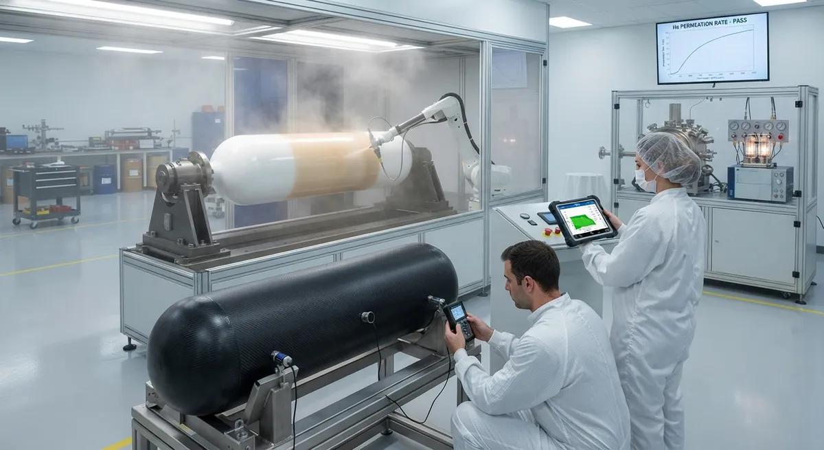
Hydrogen permeation barrier coatings are the unsung safety layer of modern composite pressure vessels. The hydrogen molecule is the smallest in existence, and it diffuses through polymers at rates far higher than natural gas or air. In a Type IV tank, where a polymer liner and carbon fiber overwrap must hold hydrogen for years, the barrier strategy determines whether the vessel meets leak-rate regulations or fails them by orders of magnitude.
This article explains why hydrogen permeates composite structures, which barrier materials actually work, how permeation is measured, and how leak-proof designs combine liners, coatings, and crack-control layers. It is written for engineers and technical buyers working on hydrogen storage tanks, pipelines, and fuel systems who need practical guidance on barrier selection and verification.
Why Hydrogen Permeates Composite Walls
Permeation is a three-step physical process: hydrogen dissolves into the material surface, diffuses through the material driven by a concentration gradient, and desorbs from the opposite surface. Polymer materials are particularly vulnerable because the diffusion happens through the free volume between polymer chains, and hydrogen's small size means it can move even through relatively tight molecular structures.
Several factors make composite tanks especially challenging:
- Small molecular diameter: Hydrogen's kinetic diameter of 0.289 nm is smaller than most polymer free-volume channels, so no polymer is an absolute barrier.
- High pressure gradients: Hydrogen tanks operate at 350-700 bar, multiplying the concentration gradient that drives diffusion.
- Temperature sensitivity: Permeation rate rises exponentially with temperature, so hot climates and solar-loaded vehicles increase leak rates.
- Matrix microcracks: Cracks in the resin matrix create short-circuit paths that bypass the liner entirely, raising permeation by orders of magnitude.
Designing a barrier therefore means both choosing a low-permeability material and protecting it from the cracks and damage that would defeat it. A barrier coating is only as good as the crack-control strategy that keeps it intact.
Barrier Material Options Compared
No single material provides an absolute hydrogen barrier, but several approaches reduce permeation by factors of 10 to 1,000 or more. The table below compares the main options for composite hydrogen tanks:
| Barrier Approach | Permeation Reduction | Temperature Range | Key Trade-off |
|---|---|---|---|
| Thermoplastic liner (HDPE, PA) | Baseline (reference) | −40°C to +85°C | Ductile and weldable, but measurable permeation |
| EVOH barrier layer | 10-100× vs HDPE | −20°C to +80°C | Brittle and moisture-sensitive; needs protection |
| Epoxy-based barrier resin | 3-10× vs HDPE | −60°C to +120°C | Process-compatible with composite overwrap |
| Metal coating (aluminum) | 100-1,000× vs HDPE | −253°C to +150°C | Crack-sensitive under flexure; adhesion critical |
| Nanocomposite (graphene/CNT loaded) | 10-100× vs HDPE | −40°C to +120°C | Dispersion quality dominates performance |
The right choice depends on service conditions. For cryogenic hydrogen at −253°C, metal-coated systems or cryogenic-grade barrier resins are required because most thermoplastics become brittle. For compressed hydrogen at ambient temperature, EVOH layers and loaded epoxy resins offer a good balance of performance and manufacturability.
Barrier Coating Application Methods
How the barrier is applied matters as much as what it is made of. A coating with pinholes, delamination, or poor coverage is worse than no coating, because it gives a false sense of safety. Common application methods include:
- In-situ polymerization on the liner: A barrier resin is applied to the polymer liner surface before filament winding, forming a chemically bonded layer that also bridges liner surface defects.
- Co-extrusion of multi-layer liners: EVOH or polyamide barrier layers are co-extruded with the structural liner polymer, creating a monolithic liner with an embedded barrier core.
- Plasma or flame surface treatment plus coating: Surface activation improves adhesion of subsequent barrier coatings, critical for metal and ceramic barrier layers.
- Physical vapor deposition (PVD): Thin aluminum or other metal films are deposited on the liner or inner overwrap surface for high-barrier applications.
- Gel-coat style spray application: A thickened barrier resin is sprayed onto the mandrel or liner surface and cured as an integral part of the laminate.
For each method, the coating thickness, adhesion strength, and coverage uniformity must be verified. A typical barrier layer is 50-500 micrometers thick for polymer systems and 1-10 micrometers for metal films, and thickness variations above 10-20% usually indicate an application process that needs correction.
Permeation Test Methods
Verifying a barrier means measuring permeation under realistic conditions. Several test methods are standardized, each suited to different stages of development:
| Test Method | Principle | Typical Use | Detection Limit |
|---|---|---|---|
| Pressure-rise / pressure-decay cell | Gas flows from a high-pressure cell into a vacuum or low-pressure cell | Coupon screening of barrier materials | 10⁻⁶ to 10⁻⁸ mbar·L/s |
| Mass-spectrometer leak detection | Helium tracer detected on the low-pressure side | Full-tank verification and assembly leak checks | Down to 10⁻¹⁰ mbar·L/s |
| Electrochemical hydrogen sensor | Electrochemical cell measures hydrogen flux through a coupon | Real-time permeation monitoring | ppb-level hydrogen flux |
| Weight-loss / gravimetric | Mass loss of a pressurized coupon or vessel over time | Long-duration storage loss measurement | 0.01 g resolution |
Test conditions must replicate service: internal pressure, temperature, and humidity all change permeation rates significantly. Hydrogen permeation at 70 MPa and 85°C can be 100 times higher than at atmospheric pressure and room temperature, so reporting a single permeation number without conditions is meaningless.
Leak-Proof Design Strategies
A leak-proof composite tank combines multiple defense layers so that no single defect creates a leak path. The design principles used in production hydrogen tanks include:
- Redundant barriers: A polymer liner plus a coating layer plus crack-resistant overwrap means permeation must fail across all layers simultaneously.
- Crack control in the overwrap: Toughened resins, fiber interleaving, and optimized winding angles suppress matrix microcracks that would create shortcut paths to the liner.
- Liner geometry design: The liner is designed to yield in a controlled way during pressurization, reducing the strain imposed on barrier layers during pressure cycles.
- Interface management: Adhesion promoters and surface treatments prevent delamination between liner, coating, and overwrap, which would otherwise trap hydrogen and create blistering.
- Monitoring and diagnostics: Embedded sensors or periodic leak testing track barrier health over the tank's service life, catching degradation before it becomes a safety issue.
These strategies are not optional extras: the international regulations for hydrogen vehicle tanks (UN R134, ISO 19882) and stationary storage require demonstrable leak-tightness over the vessel's full lifetime, including after cycling, impact, and environmental aging.
Frequently Asked Questions
Is any polymer a complete hydrogen barrier?
No. The hydrogen molecule is small enough to diffuse through the free volume of every known polymer, so every polymer barrier has a finite permeation rate. The practical question is whether the rate is low enough for the application. High-barrier approaches such as EVOH layers and loaded epoxy systems reduce permeation by 10-100 times compared with plain HDPE liners, and metal coatings reduce it by 100-1,000 times. For absolute leak-tightness over decades, a metal barrier is the most robust option, but it introduces crack and adhesion risks that must be managed. In practice, regulations define acceptable leak rates, and a properly engineered multi-layer system meets them with margin.
Why does matrix microcracking destroy permeation barrier performance?
Microcracks are through-thickness shortcuts for hydrogen. A crack in the resin matrix that connects the interior surface to the liner bypasses the barrier coating entirely, and permeation through a crack network can be orders of magnitude higher than through an intact laminate. The problem compounds over time: thermal cycling and pressure cycling grow the crack network, increasing leak rate with service life. This is why barrier coatings alone are insufficient — the overwrap must also be designed to suppress microcracking, using toughened resins, low-void laminates, and winding architectures that distribute thermal strain. A barrier system is only leak-proof when both the barrier and the structure protecting it are qualified together.
What permeation test should a buyer specify for a hydrogen composite tank?
Specify a test that covers the full tank, at the actual service pressure and temperature, and over a realistic duration. Mass-spectrometer leak detection on the pressurized full tank is the gold standard for acceptance testing, with sensitivity down to 10⁻⁸ mbar·L/s or better. In addition, require coupon-level permeation data on the barrier material across the full temperature range, because full-tank tests at a single condition miss temperature effects. For long-term confidence, require a hydrogen retention or weight-loss test that measures the actual amount of hydrogen lost over a defined period — this directly quantifies the storage efficiency customers care about. Always request the test conditions alongside the numbers: permeation data without pressure, temperature, and humidity is not interpretable.
Can a barrier coating be applied to an already-wound composite tank?
Yes, but with limitations. Post-manufacture options include spray-applied polymer coatings and in some cases vacuum-assisted metal deposition, but the adhesion surface must be prepared — usually by abrasion or plasma treatment — and coverage into complex dome regions is harder to verify. The best leak-proof performance comes from integrating the barrier during manufacture: a co-extruded multi-layer liner, or a barrier resin applied before filament winding, is continuous, well-adhered, and protected by the overwrap. Retrofitting a coating onto a finished tank is viable for demonstration projects and repairs, but for production vessels the integrated approach delivers more consistent results and is easier to qualify.
Conclusion
Hydrogen permeation barrier coatings turn a composite pressure vessel from a container that slowly loses fuel into one that meets regulatory leak limits for its entire service life. The physics is unforgiving — hydrogen leaks through everything — but layered design wins: a low-permeability barrier protected by a crack-controlled overwrap, verified by permeation tests at real service conditions. Barrier resin selection, application method, and test program must be treated as one integrated engineering decision, not three separate ones.
For engineers and buyers developing hydrogen storage tanks, the practical path is to specify measurable permeation targets, choose a barrier approach matched to the temperature and pressure envelope, and verify with full-tank leak testing after cycling. Explore our carbon fiber products for pressure vessel applications, or contact our engineering team for support on barrier integration and permeation testing for your hydrogen program.
Part of topic
Related Articles
- Carbon Fiber Drone Blades and Propellers: Stiffness, Balance and Noise Reduction
- Fiberglass Filament Wound Tubes: Cost-Effective Alternative to Carbon Fiber
- Filament Wound Epoxy Tube Design: Wall Thickness, Fiber Angle and Load Optimization
- Filament Wound Epoxy Tubes: Testing Standards and Quality Assurance
- Filament Wound Epoxy Tubes Manufacturing: Process and Quality Control
- Filament Wound Fiberglass Tube: Process Parameters and Performance vs Carbon Fiber
Interested in Our Products?
Contact our team for competitive pricing and technical specifications.
Get a QuoteRelated Products

Carbon Fiber Plate — 3K Twill T700 1.5mm
Thin 1.5mm carbon fiber plate with 3K twill weave surface. Lightweight and stiff, commonly used for covers, panels, drone bodies, and applications requiring a premium aesthetic appearance.

Custom Carbon Fiber Medical Device Components
Medical-grade carbon fiber components manufactured for imaging equipment, surgical instruments, and patient support systems. Carbon fiber's radiolucency (X-ray transparency) and high strength-to-weight ratio make it ideal for CT scanner beds, wheelchair frames, surgical robot arms, and MRI-compatible accessories. Biocompatible resin systems available.

Carbon Fiber Fishing Rod Blank
High-quality carbon fiber fishing rod blank manufactured from multiple grades of Toray carbon fiber cloth. Available in a wide range of lengths, powers, and actions for freshwater and saltwater applications. Suitable for OEM rod building.

Square Carbon Fiber Tube — 3K Twill T700
Square cross-section carbon fiber tube manufactured with 3K twill weave for torsional strength. Preferred for structural frames, trusses, and support columns where rectangular geometry offers design flexibility.
Carbon Fiber Drone Arm
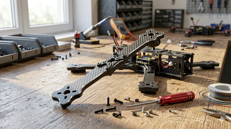
Precision-molded carbon fiber drone arm combining unidirectional fiber for stiffness and woven layers for torsional strength. Designed for FPV, photography, and industrial drone platforms. Each arm is CNC-machined to exact specifications.