
A helicopter rotor blade is a rotating beam that must do three jobs at once: carry centrifugal force from the rotation, resist flap bending from lift, and absorb lag bending from drag. Add the fact that each blade completes thousands of load cycles per hour of flight, and it becomes cle
Introduction
A helicopter rotor blade is a rotating beam that must do three jobs at once: carry centrifugal force from the rotation, resist flap bending from lift, and absorb lag bending from drag. Add the fact that each blade completes thousands of load cycles per hour of flight, and it becomes clear why metal blades reached their practical limit decades ago. Composite blades — carbon fiber spars with glass or hybrid skins — now fly on virtually every modern rotorcraft because they combine high specific strength with a fatigue behavior that does not show the aluminum blade's classic sudden crack growth.
The composite rotor blade story is really three engineering stories: how the spar is designed and manufactured to resist torsion as well as bending, how the leading edge is protected from sand and rain erosion that would otherwise shorten blade life to months, and how the certification process demonstrates a fatigue life of 10,000 hours or more. Each of these determines the maintenance economics that operators live with for the blade's entire service life.
Blade Architecture: The Spar Is the Structure
Modern rotor blades use a spar-skin (or spar-rib) architecture. The spar — typically a D-shaped or C-shaped section at the blade leading edge — is the primary load path; the skin and core fill the trailing-edge box for aerodynamics and torsional stiffness.
- Spar: unidirectional carbon fiber, often with trailing-edge plies at moderate angles, carrying centrifugal, flap and lag loads.
- Skin: woven glass and carbon fabric, protecting the core and contributing torsional stiffness and impact resistance.
- Core: foam or honeycomb filling the trailing-edge region, giving the airfoil shape without weight.
- Torsion box: the closed section formed by spar, skin and root fitting that transmits pitch control torque from the pitch horn to the blade tip.
- Root end: a tapered laminate transition bonded to the metallic grip that carries the blade's pitch and lead-lag bearings.
The design freedom of composites lets engineers tailor fiber orientation along the span — high 0-degree content at the root where centrifugal load peaks, more angle at mid-span where torsion dominates — something a metallic extrusion cannot do at all.
Spar Torsion Design: The Torsion-Stiffness Problem
Torsion is the discipline that separates a good rotor blade spar from a marginal one. Pitch control rotates the blade about its feathering axis through the pitch horn, and the blade must twist to the commanded angle from root to tip with minimal phase lag. If the spar is too torsionally soft, the blade lags the control input, causing pitch-flap coupling that can destabilize the rotor.
Carbon fiber is the answer because its specific torsional stiffness is far higher than glass fiber in the same laminate weight. The spar layup is a balance of three load cases:
| Load case | Principal loading | Layup response |
|---|---|---|
| Centrifugal | Maximum at root, tensile | High 0-degree unidirectional content |
| Flap and lag bending | Alternating, vibration governed | 0-degree plus ±45-degree plies for damage tolerance |
| Torsion | Pitch input transmitted root to tip | ±45-degree plies closing the torsion box |
The torsion-box design keeps the load path closed: the spar's trailing edge and the skin together form a tube that transmits torque efficiently. A typical main rotor blade needs a torsional stiffness such that the nose-down pitch angle changes by only a few degrees from root to tip under full control input, and the ±45-degree carbon plies in the torsion box are what guarantees it.
Leading-Edge Erosion Protection
Erosion is the blade's most frequent failure mechanism in hard service. Sand, dust, rain and ice crystals impact the leading edge at tip speeds that can exceed 200 m/s on large rotors, and unprotected composite edges erode rapidly. The result is a loss of airfoil performance, then exposure of the underlying laminate to moisture. Protection systems in production use three approaches:
- Polyurethane tape and coatings: flexible coverings that absorb impact energy; replaced on schedule, they protect the laminate underneath for the life of the blade.
- Nickel or titanium leading-edge sheath: a metal sheath bonded over the spar nose on blades flying in severe sand and rain environments, offering the longest life but adding weight and manufacturing complexity.
- Strain-tolerant elastomeric layers: used where chordwise bending is high, absorbing both erosion and flex without cracking.
For most operators the compromise is a replaceable polyurethane erosion shield on the outboard two-thirds of the blade, where tip speed is highest, combined with scheduled tape replacement. The erosion system is a maintenance item by design: it is cheaper to replace a 200-gram polymer shield every few hundred hours than to re-skin a blade.
Fatigue Certification and the 10,000-Hour Life Target
Rotor blade certification is dominated by fatigue. Aluminum blades exhibited a quiet but real crack-initiation life; composite blades fail differently — gradually, in damage tolerance terms — and the certification regime is designed around proving that the blade stays airworthy across a scatter of manufacturing, usage and damage variables.
- Full-scale fatigue testing: one blade test article undergoes accelerated cycling equivalent to tens of thousands of flight hours, loading the blade in combined centrifugal, flap, lag and torsion.
- Damage tolerance demonstration: test blades with seeded impact damage — the equivalent of a hangar strike or stone impact — must still reach the design life without catastrophic crack growth.
- Scatter factor: certification divides demonstrated life by a scatter factor (typically 4-5) to set the approved service life, absorbing test-to-test and blade-to-blade variability.
- In-service fleet management: statistical tracking of blade usage, plus scheduled NDT, extends or refines the approved limits over time.
The 10,000-hour-plus main rotor blade life targets that now appear in type certificates are the payoff: with a 4-5x scatter factor applied, reaching 10,000 approved hours requires demonstrating more than 40,000 equivalent hours in testing — a physics-of-failure regime in which composites, not metal, are the material that closes the gap.
Manufacturing and Inspection in Service
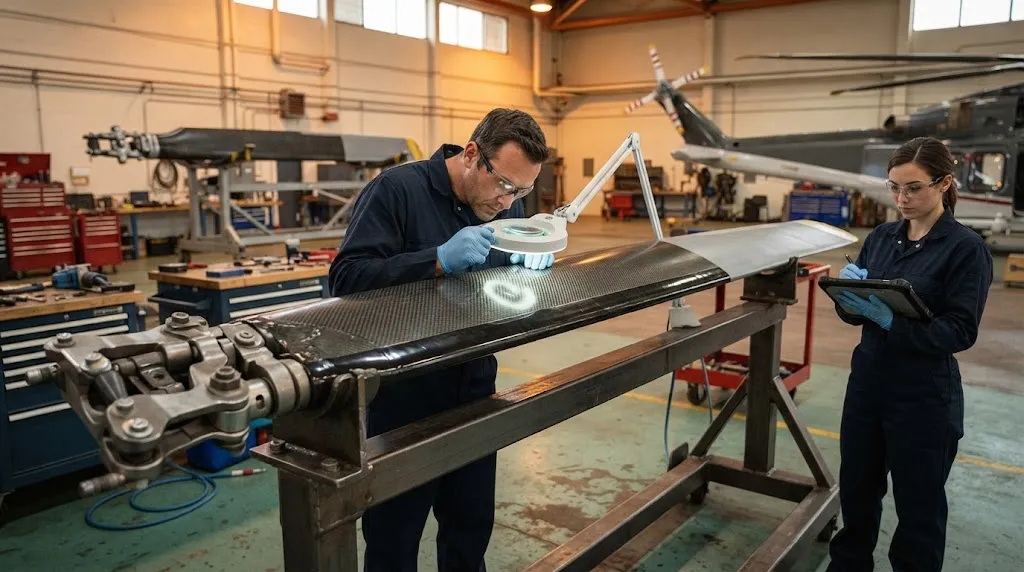
Production blades are manufactured by layup of prepreg on a male spar mandrel, then pressing the spar and skin together in a matched-die or autoclave cycle. Wrinkle control in the spar radii is the critical quality gate, because fiber wrinkles at the nose radius are the classic initiation sites for both static and fatigue failure. In service, blades are inspected on a calendar-plus-usage schedule:
- Visual and tap inspection: at short intervals, detecting erosion, impact and disbond at surfaces.
- Ultrasonic phased array: scheduled checks of the spar and bond lines for delamination and porosity.
- Thermography and shearography: used on specific blade models for bond-line assessment between skin, core and spar.
This inspection program converts the blade's damage tolerance into operational safety: because a composite blade degrades gradually and can carry load well past first damage, the interval between inspections is designed to catch any growth long before it becomes critical.
Frequently Asked Questions
Why are helicopter rotor blades made of composites instead of aluminum?
Composite blades combine high specific strength with damage-tolerant fatigue behavior: rather than the sudden crack growth of aluminum, composites degrade gradually and retain significant strength after impact damage. Composites also allow tailoring of fiber orientation along the span, giving spar designers independent control over centrifugal, bending and torsion stiffness that a metallic extrusion cannot achieve.
How does a composite rotor blade handle torsional loads from pitch control?
The blade is designed as a torsion box: the spar's trailing-edge region and the skin together form a closed section that transmits pitch torque efficiently. ±45-degree carbon plies in the torsion box provide the specific torsional stiffness needed so the blade tracks pitch inputs from root to tip with only a small phase lag, avoiding destabilizing pitch-flap coupling.
What protects composite rotor blade leading edges from erosion?
Production blades use polyurethane tape or coatings, metallic (nickel or titanium) leading-edge sheaths, or strain-tolerant elastomeric layers. The flying environment decides the choice: replaceable polymer shields suit most operators, while severe sand and rain environments justify bonded metal sheaths despite the weight and complexity penalty.
How is a 10,000-hour blade life certified?
Through full-scale fatigue testing equivalent to tens of thousands of flight hours with combined load cycling, damage tolerance demonstration on impacted test blades, and a scatter factor (typically 4-5) between demonstrated and approved life. Reaching 10,000 approved hours requires demonstrating over 40,000 equivalent hours in testing.
Conclusion
Composite rotor blades have moved from experimental to universal because they solve the three problems that define rotorcraft economics: combined centrifugal-flap-lag loading, torsion response for pitch control, and erosion resistance that protects the airfoil against the environment. The spar's unidirectional carbon content carries the loads, the ±45-degree torsion box transmits pitch without lag, and polyurethane or metallic shields absorb erosion. Fatigue certification through scatter-factor-divided full-scale testing underpins the 10,000-hour-plus lives that keep composite blades competitive on maintenance cost per flight hour.
YongXian supplies aerospace-grade carbon fiber unidirectional prepreg, woven fabrics and torsion-friendly intermediate-modulus materials for rotor blade programs. Explore our aerospace product range or contact our engineering team to discuss material systems for rotorcraft structures.
Part of topic
Related Articles
- Carbon Fiber Mooring for Floating Offshore Wind: Fatigue and Corrosion in Deep Water
- Carbon Fiber Bicycle Frame Optimization: Layup Design and Manufacturing for Competitive Racing
- Carbon Fiber CFRP Retrofit for Infrastructure: Bridge and Building Seismic Strengthening
- Carbon Fiber Medical Imaging Equipment: Lightweight Gantry and Couch Structures for MRI/CT
- Carbon Fiber EV Battery Enclosures: Crash Safety and Electromagnetic Shielding Design
- Carbon Fiber Structures for Low-Altitude Economy: UAV Airframes and eVTOL Components