
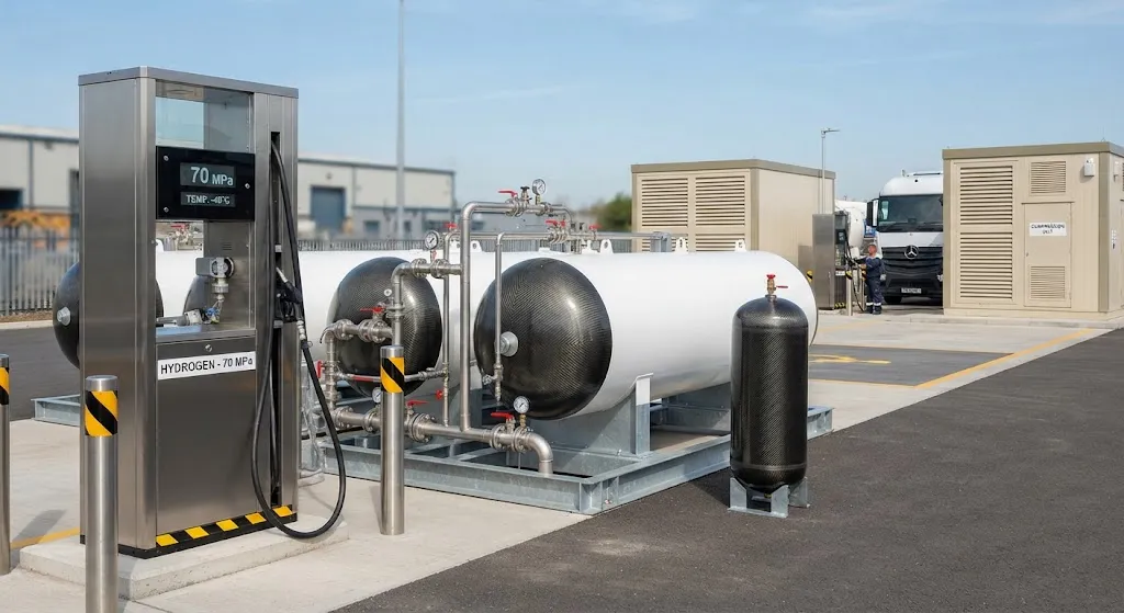
A hydrogen refueling station is a pressure system arranged around one question: how to hold high-pressure gas between delivery and dispensing. Between the incoming hydrogen — truck-delivered, pipeline-fed, or made on site by electrolyzer — and the vehicle tank, the station needs buffer
Introduction
A hydrogen refueling station is a pressure system arranged around one question: how to hold high-pressure gas between delivery and dispensing. Between the incoming hydrogen — truck-delivered, pipeline-fed, or made on site by electrolyzer — and the vehicle tank, the station needs buffer volume to smooth compressor duty and cascade banks at staggered pressures to fill vehicles efficiently. Almost all of that intermediate storage now sits in composite pressure vessels, and ground storage at stations plus grid-scale energy storage accounts for roughly 30 percent of global hydrogen tank demand, according to IndexBox market data.
This article walks through the station architecture, compares the four vessel types on the numbers that actually decide station economics, and lays out the fatigue, safety, and code logic that keeps composite tanks at the heart of hydrogen refueling infrastructure.
Station Storage Architecture
A typical station holds hydrogen in a cascade: several banks of vessels charged to different pressure levels, so the dispenser can fill a vehicle from the lowest bank that still has enough pressure, then step up, leaving the compressors and buffer volume to top the banks back up. Light-duty cars dispense at 70 MPa, while heavy trucks and buses commonly fill at 35 MPa — roughly half the pressure, which changes both vessel and compressor economics. Because gas heats when compressed, 70 MPa dispensing requires precooling the hydrogen to about minus 40 degrees Celsius at the dispenser, which adds a chilling loop the station must manage.
Scale matters as much as pressure. A station serving a few buses might hold 200-300 kilograms of stored hydrogen; a busy multi-vehicle hub can hold more than 1,000. Compressors raise moderate delivery pressure to storage pressure in stages, and the buffer tanks absorb the difference between steady compressor output and the burst demand of a vehicle fill. The vessel banks, not the compressor, carry most of the station's capital in storage capacity — which is why the choice of vessel type is a station-design decision, not a component detail.
Vessel Types Used at Stations
Station ground storage spans all four pressure vessel families. The table summarizes the trade-offs as they apply to refueling stations:
| Vessel Type | Typical Service Pressure | Liner / Construction | Relative Cost per kg Stored | Cycle Life Characteristics | Station Role |
|---|---|---|---|---|---|
| Type I | 10-30 MPa | All-metal steel | Lowest | Robust bulk cycling | Low-pressure buffer volume |
| Type II | 20-45 MPa | Steel liner, CFRP hoop wrap | Low-moderate | Good fatigue with thick metal liner | Dominant bulk ground storage |
| Type III | 35-70 MPa | Metal liner, full CFRP wrap | High | Full-wrap reduces liner fatigue | 70 MPa cascade banks |
| Type IV | 35-87.5 MPa | Polymer liner, full CFRP wrap | Highest, lightest | Best fatigue per unit mass | 70 MPa banks, capacity-dense sites |
The pattern is economic as much as technical. Type I and Type II vessels carry the low-to-mid pressure volume cheaply — a steel liner carries the stress, and the hoop wrap on a Type II adds circumferential strength where the wall stress peaks, roughly doubling allowable pressure for a modest fiber investment. Type III and Type IV go full-wrap for the 70 MPa service pressures that passenger-car dispensing demands, where the liner must be either thick enough to resist fatigue or removed entirely from the stress path, as in the polymer-lined Type IV. For a fixed station site, the trade between Type II bulk banks and Type IV high-pressure banks is decided by how much 70 MPa capacity the vehicle mix actually needs.
Design Drivers: Fatigue, Cost, and Safety
Station vessels cycle differently from vehicle tanks, and the design reflects it. A vehicle cylinder fills and empties a few times a day; a station buffer tank can cycle many times per day as compressors charge it and dispensers drain it. The fatigue spectrum is dominated by partial cycles — pressure swings between bank minimum and compressor setpoint rather than full blowdowns — so fatigue life is designed around realistic duty cycles, not worst-case assumptions. Full-wrap composites handle this well because the fiber carries the load and the liner, if metal, is supported by pre-stress from the wrap; polymer liners in Type IV vessels simply do not fatigue like steel.
Safety and codes come from a settled framework. Station design follows ISO 19880-1, the international standard for gaseous hydrogen fueling stations; vehicle fueling protocols follow SAE J2601, which governs fill rate, pressure, and precooling for light-duty vehicles; and vehicle cylinders themselves fall under UN ECE R134 and comparable national regulations. Design burst pressure for high-pressure hydrogen vessels is typically 2.25 times service pressure, a margin that stations usually stretch further because ground installations carry no weight constraint and can afford thicker wraps. The composite layer is designed so that failure modes are detectible — leakage before burst — and station layouts enforce separation distances that protect surrounding infrastructure.
Compression energy is the hidden cost. Raising gas from delivery pressure to 70 MPa storage costs real electricity, roughly 3-5 kWh per kilogram depending on final pressure and efficiency, so stations that store most of their hydrogen at moderate pressure and boost only for dispensing keep their energy bills down. The buffer strategy — compress steadily, store, dispense in bursts — is what makes a station run its compressor at efficient operating points instead of chasing every vehicle arrival.
Market Outlook and Demand Drivers
Refueling infrastructure has crossed from pilot to program scale. More than a thousand public hydrogen refueling stations now operate worldwide, with China, Europe, South Korea, and Japan leading the counts — South Korea alone runs one of the densest national networks in absolute numbers, and China's provincial targets continue to push triple-digit annual growth. Heavy transport is the demand center of gravity: a single bus consumes orders of magnitude more hydrogen than a car, so stations sized for fleets dominate the tonnage moved. The buffer and cascade vessels at those stations are recurring infrastructure demand — installed once per site, replaced on fatigue life — which is why IndexBox groups station storage with grid-scale buffering at about 30 percent of global tank demand.
- Choose Type II hoop-wrapped vessels for bulk low-to-mid pressure storage; they carry the most storage per dollar on a fixed site.
- Specify full-wrap Type III or Type IV vessels for 70 MPa cascade banks serving light-duty vehicles.
- Design for partial-cycle fatigue with realistic daily duty spectra, not full-blowdown assumptions.
- Budget compression energy: storing at moderate pressure and boosting for dispensing beats storing everything at 70 MPa.
- Qualify vessels to ISO 19880-1 station requirements and follow SAE J2601 fill protocols at the dispenser.
Frequently Asked Questions
Why not store all station hydrogen at 70 MPa and skip the cascade?
Compression energy and vessel cost both punish it. Pushing every kilogram up to 70 MPa costs roughly 3-5 kWh of compression per kilogram and forces every storage vessel onto the expensive full-wrap family; storing the bulk at 20-45 MPa in Type II vessels and boosting only what dispensing needs cuts both. The cascade exists because vehicle fill requirements are pressure-staged — a nearly empty vehicle tank can start from a moderate-pressure bank, and only the last portion of the fill needs the highest pressure.
Do station buffer tanks fail from fatigue like vehicle cylinders?
They fatigue from a different spectrum: many partial cycles per day rather than a few full ones. Type IV polymer-lined vessels remove liner fatigue almost entirely, and metal-lined full-wrap types are supported by wrap pre-stress. Station vessels are also designed with a 2.25-times-service burst margin or higher, because ground installations carry no weight limit. The practical failure modes are leak-before-burst, which station gas detection systems catch, not sudden rupture.
How much does station storage cost per kilogram of hydrogen?
Representative figures for bulk ground storage land around 1,300-2,900 USD per kilogram of storage capacity, before compression and installation, with Type I and Type II at the low end and full-wrap high-pressure vessels at the high end. The spread is why station designers load most of the stored volume into the cheapest vessel family that still meets the dispensing pressure profile — the composite choice is a direct line item in station capital cost.
Conclusion
Hydrogen refueling station storage has converged on one architecture: cascade banks of composite vessels that hold the pressure, buffer the compressor, and dispense 35 or 70 MPa to vehicles under ISO 19880-1 rules. Type II hoop-wrapped vessels carry the bulk volume cheaply; Type III and Type IV full-wrap vessels own the high-pressure banks; and the fatigue design follows a partial-cycle duty spectrum that composites handle better than metal ever did. With station storage and grid buffering approaching 30 percent of global tank demand, the composite pressure vessel is not an accessory to the hydrogen economy — it is the tank farm under every dispenser.
For engineers designing or upgrading station storage, the fiber and winding choice starts the economics. Explore our pressure vessel grade carbon fiber, or contact our team to discuss vessel qualification and supply for your hydrogen infrastructure program.
Part of topic
Related Articles
- Carbon Fiber Plate Amazon: Complete Guide
- Carbon Fiber And PU Case: Complete Guide
- Carbon Fiber Parts For Cars: Complete Guide
- Carbon Fiber Manufacturing Companies: Complete Guide
- Carbon Fiber Parts Manufacturing: Complete Guide
- Carbon Fiber Sheets for Sale: A Buyer Checklist for Thickness, Weave and Finish
Interested in Our Products?
Contact our team for competitive pricing and technical specifications.
Get a QuoteRelated Products

Round Carbon Fiber Tube — UD Unidirectional T700
Unidirectional (UD) round tube with all fibers aligned axially for maximum longitudinal stiffness. Ideal for applications requiring high bending rigidity with minimal weight, such as shafts, struts, and structural reinforcements.

Carbon Fiber Plate — High-Gloss Decorative
High-gloss decorative carbon fiber plate with a mirror-like surface finish. The glossy coating enhances the visible 3K twill weave, creating a premium aesthetic for consumer-facing applications. Lightweight yet stiff, available in thin gauges for easy cutting and forming.

High Modulus Round Carbon Fiber Tube — M40
High modulus round tube manufactured with M40 grade fiber (tensile modulus 400 GPa). Designed for applications where maximum stiffness-to-weight ratio is critical, such as optical systems, precision machinery, and aerospace structures.