Carbon fiber plate for robotics shows up wherever moving mass costs cycle time: six-axis arm links, gripper jaws, mobile chassis decks, and sensor mounts that must stay rigid without dragging the payload budget. The appeal is straightforward - high specific stiffness, low inertia, and a flat stock f
Introduction
Carbon fiber plate for robotics shows up wherever moving mass costs cycle time: six-axis arm links, gripper jaws, mobile chassis decks, and sensor mounts that must stay rigid without dragging the payload budget. The appeal is straightforward - high specific stiffness, low inertia, and a flat stock form that machine shops already know how to cut. The traps are just as familiar: wrong thickness, uncontrolled tolerances, and suppliers who sell plate without understanding how robots load it.
This article covers the design rules for carbon fiber plate used on robots, the specs to put on a drawing, and how to move from a carbon fiber plate custom prototype to a repeatable production source.
Design Loads for Carbon Fiber Plate for Robotics
Robot links see combined bending, torsion, and bolt preload rather than simple uniform pressure. Start with the worst-case payload at full extension, add dynamic factors for acceleration and emergency stops, then check deflection at the tool face - vision systems and mating flanges care more about microns of tip droop than about ultimate strength. Plate thickness follows from that deflection limit; fibre orientation follows from the dominant load path. Quasi-isotropic layups behave predictably in every direction and are the default for general robotics plates; biased or unidirectional stacks save weight when the load is clearly one-way, such as a long gripper finger. Documenting these assumptions in the drawing notes keeps the supplier from guessing at a safety factor that does not match your control system.
For high-cycle pick-and-place cells, fatigue deserves its own line in the spec. Carbon laminates tolerate many cycles when fibre strain stays in the elastic window, but hole edges, countersinks and bonded inserts concentrate stress. A conservative design keeps working strain low, avoids sharp ply drops near bolt groups, and uses load-spreading washers or bonded bushings at high-load interfaces. If the robot operates in a washdown or coolant-mist environment, seal machined edges and confirm the resin system is compatible with the cleaning chemistry.
| Robot zone | Dominant load | Typical thickness | Spec emphasis |
|---|---|---|---|
| Arm link covers | Inertia, vibration | 1.5 to 3 mm | Flatness, surface finish, light weight |
| End-effector base | Bending from grip moment | 4 to 6 mm | Hole pattern tolerance, stiffness at tool face |
| Mobile chassis deck | Point loads from mounts | 5 to 8 mm | Impact resistance, insert readiness |
| Sensor brackets | High-frequency vibration | 2 to 4 mm | Resonance, damping, repeatable edges |
Treat the table as a starting band, not a substitute for calculation. If two thicknesses both pass, prefer the stocked size so carbon fiber plate price stays in standard tiers instead of custom press minimums.
Machining Rules for Robotics Plate
Carbon fiber plate for robotics is almost always CNC machined after cure. Sharp tooling, dust extraction, and conservative chip loads protect both the fibre and the operator; abrasive dust will ruin unprotected spindles and lungs alike. Avoid sharp internal corners in pockets - leave a radius that keeps plies continuous. Counterbores need enough land for washer bearing area without breaking through into unsupported laminate. When locating accuracy matters, machine critical faces after stress relief rather than trusting as-pressed flatness alone. Label the machining datum scheme on the drawing so inspection and assembly reference the same coordinate system, and call out which faces are cosmetic versus functional.
- Hole patterns: put datums on the drawing and machine the pattern in one setup to preserve position tolerance.
- Edge sealing: seal machined edges on parts exposed to coolant or outdoor humidity.
- Inserts: use bonded or over-moulded metal inserts for repeated assembly cycles instead of threading directly into laminate.
- Acceptance: request a first-article report covering thickness, flatness, and true position before releasing the production lot.
From Prototype to Production: Carbon Fiber Plate Custom Programs
A carbon fiber plate custom program is how robotics teams move past one-off waterjet orders. The supplier holds stock grades and thicknesses, cuts blanks to your nest, machines critical features, and kits parts against your assembly schedule. That model amortizes fixturing across many units, which is why unit price falls faster on custom plate programs than on pure material sales. Confirm who owns the nest files and jugs of tooling, how first articles are approved, and what happens to skeleton material after your cut plan runs - those three questions separate a real program from a job shop with a catalogue.
Price drivers on carbon fiber plate for robotics are predictable: fibre grade (T300 class versus higher-strength T700), weave style, thickness tolerance class, and how much machining is in the statement of work. Material dominates on thick, lightly machined plates; operations dominate on thin, hole-dense gripper parts. Ask for the split in the quote so you know where to negotiate when volumes rise.
Frequently Asked Questions
Is carbon fiber plate better than aluminum for robot arms?
For moving links and end effectors, carbon fiber plate usually wins on stiffness-to-weight, which lowers inertia and lets a given motor move more payload. Aluminum remains simpler for heat spreading, welding, and low-volume fixtures where machining time matters more than mass. Hybrid designs are common: carbon plate structure with aluminum interface blocks where screws and cooling live.
How thick should a carbon fiber plate for robotics gripper base be?
Most gripper bases land between 4 mm and 6 mm when the grip moment is carried in bending over a short span. Below 3 mm, tip deflection often shows up as dropped parts or vision misalignment; above 8 mm, you are usually paying for stiffness the mount already provides. Run a quick deflection check with the actual jaw length before fixing the thickness on the drawing.
Can suppliers deliver machined carbon fiber plate custom parts, not just sheet?
Yes, if you confirm machining capability during quotation. Ask for CNC envelope size, tolerance classes on holes and edges, first-article documentation, and whether edge sealing and inserts are in scope. A supplier that only sells flat stock will push you to a separate machine shop, which works for prototypes but complicates revision control in production.
Conclusion
Specifying carbon fiber plate for robotics comes down to four decisions: load case and deflection limit, stocked thickness with the right tolerance class, machining and insert strategy, and a custom plate program that scales with your build rate. Get those right and the material earns its place through lower inertia and higher rigidity; get them wrong and you pay for scrap and rework. To review plate grades, machining options and carbon fiber plate price tiers, browse the carbon fiber products catalogue or contact the technical sales team with your robot loads, hole pattern and annual volume for a written proposal.
Part of topic
Related Articles
- Carbon Fiber Sheet for Furniture: Design, Specs and Sourcing | YongXian
- Carbon Fiber Plate for Medical Device: Design, Specs and Sourcing | YongXian
- Carbon Fiber Sheet for Sporting Goods: Design, Specs and Sourcing | YongXian
- Carbon Fiber Sheet for Automotive Parts: Design, Specs and Sourcing | YongXian
- Carbon Fiber Rod for Fishing Rod Blank: Design, Specs and Sourcing | YongXian
- Carbon Fiber Tube for Bicycle Frame: Tube Sets, Joints and Sourcing | YongXian
Interested in Our Products?
Contact our team for competitive pricing and technical specifications.
Get a QuoteRelated Products
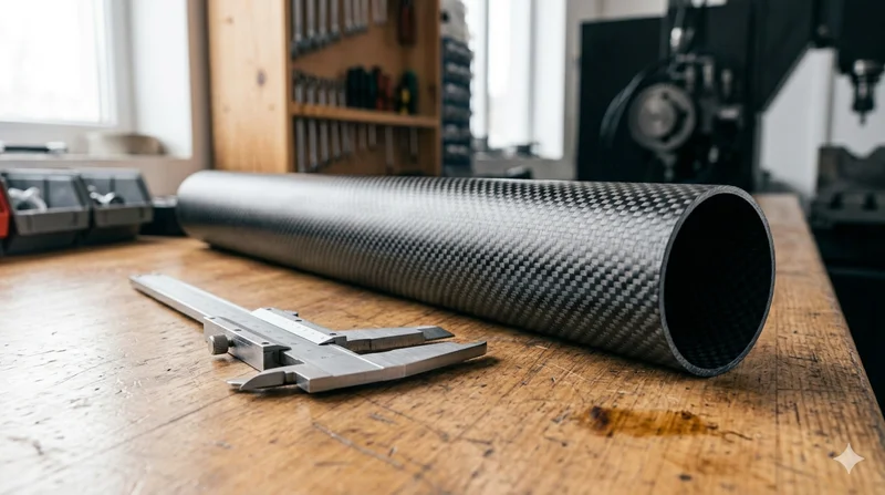
Round Carbon Fiber Tube — 3K Plain Weave T700
Standard round carbon fiber tube manufactured from Toray T700 grade fiber with 3K plain weave. Offers balanced strength and stiffness for general industrial applications including robotics, automation, sports equipment, and aerospace structures.
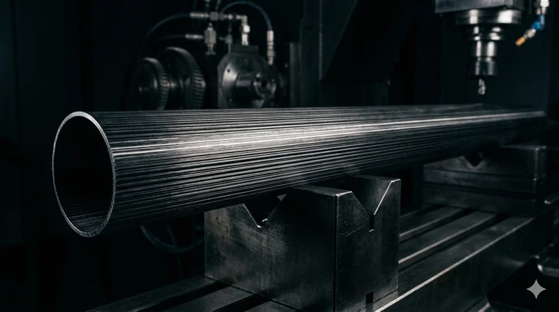
Round Carbon Fiber Tube — UD Unidirectional T700
Unidirectional (UD) round tube with all fibers aligned axially for maximum longitudinal stiffness. Ideal for applications requiring high bending rigidity with minimal weight, such as shafts, struts, and structural reinforcements.
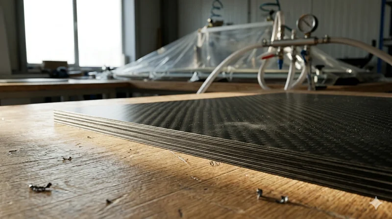
Carbon Fiber Plate — 3K Twill T700 3.0mm
Medium-thickness 3.0mm carbon fiber plate offering significantly higher load capacity while maintaining attractive 3K twill finish. Suitable for structural brackets, reinforcement plates, and load-bearing panels.
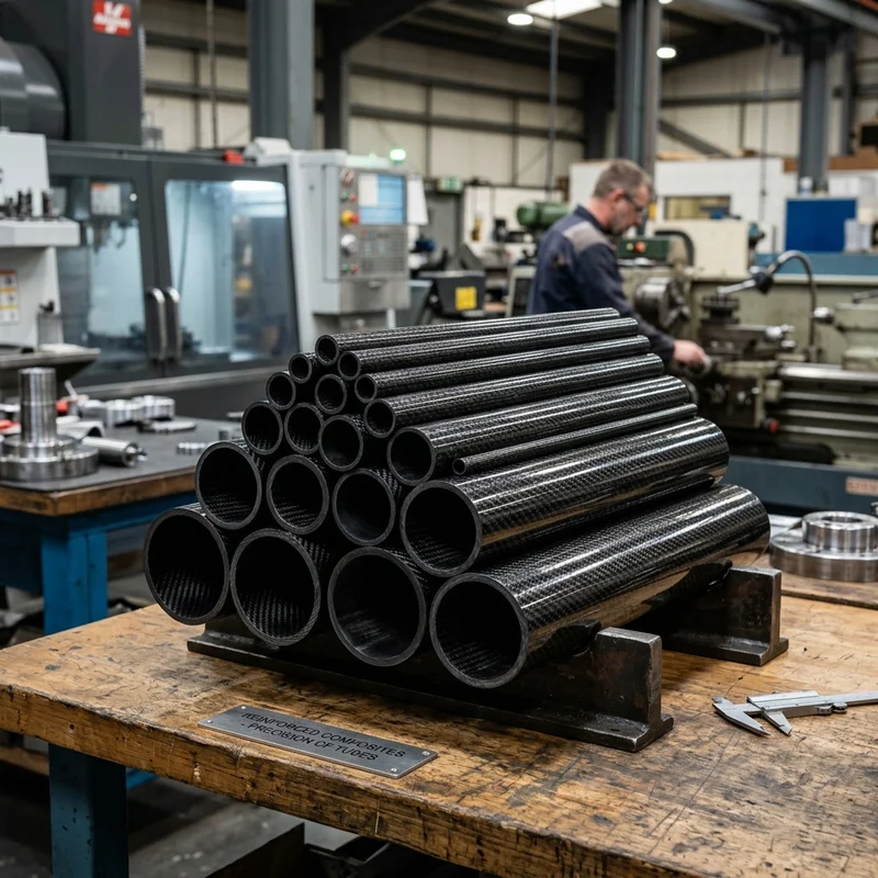
Round Carbon Fiber Tube — 3K Twill
Lightweight and ultra-stiff round tubes ideal for drone frames, robotics, and structural applications.
Carbon Fiber Plate — 3K Twill T700 1.5mm
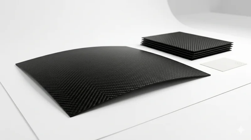
Thin 1.5mm carbon fiber plate with 3K twill weave surface. Lightweight and stiff, commonly used for covers, panels, drone bodies, and applications requiring a premium aesthetic appearance.